Chapter 2: System hardware
97
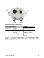
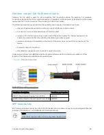
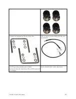
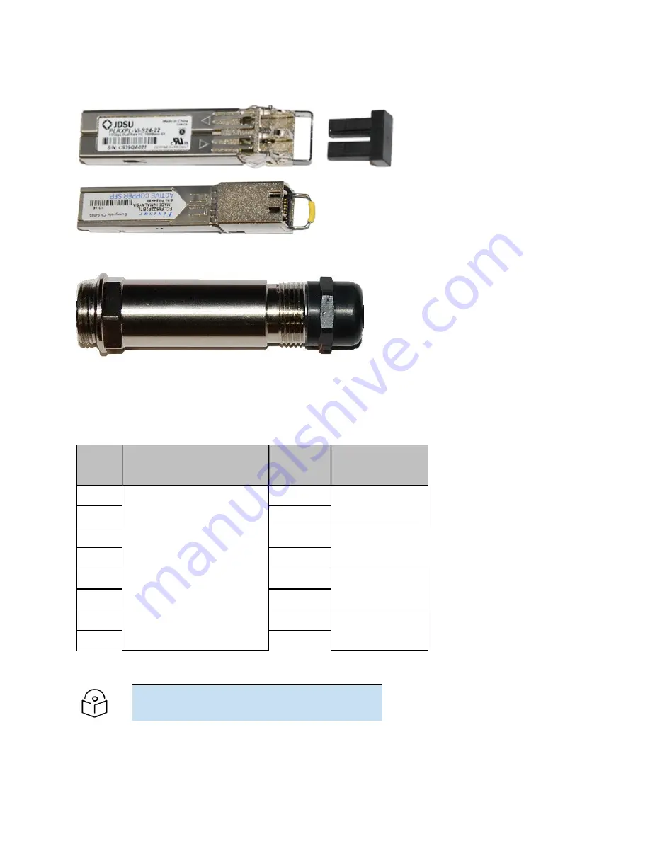
Figure 32 :
Optical SFP transceiver module
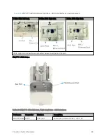
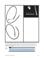
Figure 33 :
Long cable gland
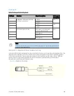
Main Et her net p or t
The PoE cable pinout diagram for Main port is given below.
Table 69 :Main port PoE cable pinout
RJ45
pin
Interface
Ethernet
description
PoE input
description
1
1000 BaseT Ethernet with
PoE In
+TxRx0
+Ve or -Ve
2
–TxRx0
3
+TxRx1
+Ve or –Ve
6
–TxRx1
4
+TxRx2
+Ve or –Ve
5
–TxRx2
7
+TxRx3
+Ve or –Ve
8
–TxRx3
Note
The PoE input on the Main port accepts any polarity.
Summary of Contents for PMP 450 Series
Page 92: ...Chapter 2 System hardware 92 Figure 29 MicroPoP Omni antenna implementation pattern Vertical...
Page 134: ...Chapter 3 System planning 134 Figure 51 Mast or tower installation...
Page 135: ...Chapter 3 System planning 135 Figure 52 Wall installation...
Page 136: ...Chapter 3 System planning 136 Figure 53 Roof installation...
Page 137: ...Chapter 3 System planning 137 Figure 54 GPS receiver wall installation...
Page 158: ...Chapter 3 System planning 158 Figure 61 cnMedusa Antenna...


