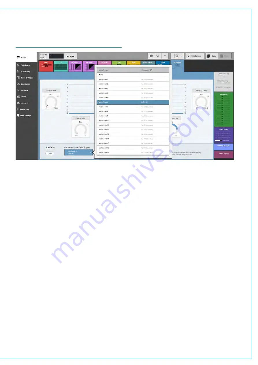
Assigning autofaders to faders
Once the relevant GPIs have been assigned to autofaders, the autofaders can be assigned to control faders on the
surface. This is done on the Access>AutoFader screen as shown in Figure 3.
FIGURE 3 - ASSIGNING AUTOFADERS TO FADERS
Autofader levels
When an autofader is attached to a fader and is enabled, providing the trigger signal is not present, the fader will go
to the OUT LEVEL complying with the Fade-Out Duration parameter, rather than snapping the audio to the Fade-Out
level. If an AutoFader is enabled, either from path or global enable, for a path whose GPI is currently triggered, the audio
should fade (up or down) to the Fade-In Level (if it is not there already), complying with the Fade-In Duration parameter,
rather than snapping the audio to the Fade-In level. When the trigger signal is present, the fader will follow the settings
made on the Access>AutoFader screen.
Autofader parameter settings
The AUTOFADER screen allows the settings of the autofaders to be configured. The available settings for all the Time
based controls are :
•
0 to 100ms in 10ms steps.
•
100ms to 1s in 100ms steps.
•
1s to 5s in 500ms steps.
The IN and OUT gain level settings are -100dB to +10dB.
Global Autofader Bypass
At the bottom of the AutoFader screen there is a copy of the Global Bypass button which effectively disables all
Autofaders.
Autofader indicators
When an autofader is assigned to a fader, the Fader display will show the AutoFader Number and the Meter display
shows when the AutoFader is active.
Summary of Contents for SUMMA
Page 11: ...V3 0 196 V3 1 197 V3 1 1 197 V3 2 197 CALREC Putting Sound in the Picture 11...
Page 12: ...12 SUMMA Networked Audio Production System CONTENTS...
Page 13: ...PRODUCT INFORMATION calrec com Putting Sound in the Picture SUMMA...
Page 20: ...20 SUMMA Networked Audio Production System PRODUCT INFORMATION...
Page 21: ...SYSTEM OVERVIEW calrec com Putting Sound in the Picture SUMMA...
Page 33: ...CALREC Putting Sound in the Picture 33...
Page 38: ...38 SUMMA Networked Audio Production System SYSTEM OVERVIEW...
Page 52: ...52 SUMMA Networked Audio Production System SYSTEM OVERVIEW...
Page 53: ...SETTING UP calrec com Putting Sound in the Picture SUMMA...
Page 55: ...FIGURE 1 SYNCHRONISATION OPTIONS CALREC Putting Sound in the Picture 55...
Page 74: ...74 SUMMA Networked Audio Production System SETTING UP...
Page 75: ...GETTING SIGNALS IN AND OUT calrec com Putting Sound in the Picture SUMMA...
Page 93: ...FIGURE 4 SOURCE AND DESTINATION POP UP MEMORY LOAD CALREC Putting Sound in the Picture 93...
Page 105: ...MONITORING calrec com Putting Sound in the Picture SUMMA...
Page 107: ...FIGURE 2 EXAMPLE LOUDSPEAKERS SETUP CALREC Putting Sound in the Picture 107...
Page 110: ...FIGURE 1 THE MONITORING POP UP 110 SUMMA Networked Audio Production System MONITORING...
Page 113: ...METERING calrec com Putting Sound in the Picture SUMMA...
Page 121: ...calrec com Putting Sound in the Picture SUMMA PROCESSING...
Page 153: ...COMMUNICATIONS calrec com Putting Sound in the Picture SUMMA...
Page 161: ...FIGURE 4 MIX MINUS CONTRIBUTION POP UP CALREC Putting Sound in the Picture 161...
Page 163: ...ROUTING calrec com Putting Sound in the Picture SUMMA...
Page 165: ...FIGURE 1 CONFIGURING BUSES AND OUTPUTS CALREC Putting Sound in the Picture 165...
Page 171: ...EXTERNAL INTERFACING calrec com Putting Sound in the Picture SUMMA...
Page 179: ...FIGURE 2 LAN CONFIGURATION WINDOW CALREC Putting Sound in the Picture 179...
Page 180: ...180 SUMMA Networked Audio Production System EXTERNAL INTERFACING...
Page 181: ...CONSOLE FACILITIES calrec com Putting Sound in the Picture SUMMA...
Page 187: ...TERMINOLOGY calrec com Putting Sound in the Picture SUMMA...
Page 195: ...FEATURES BY SOFTWARE VERSION calrec com Putting Sound in the Picture SUMMA...


