CUSTOM STRIP CONFIGURATION
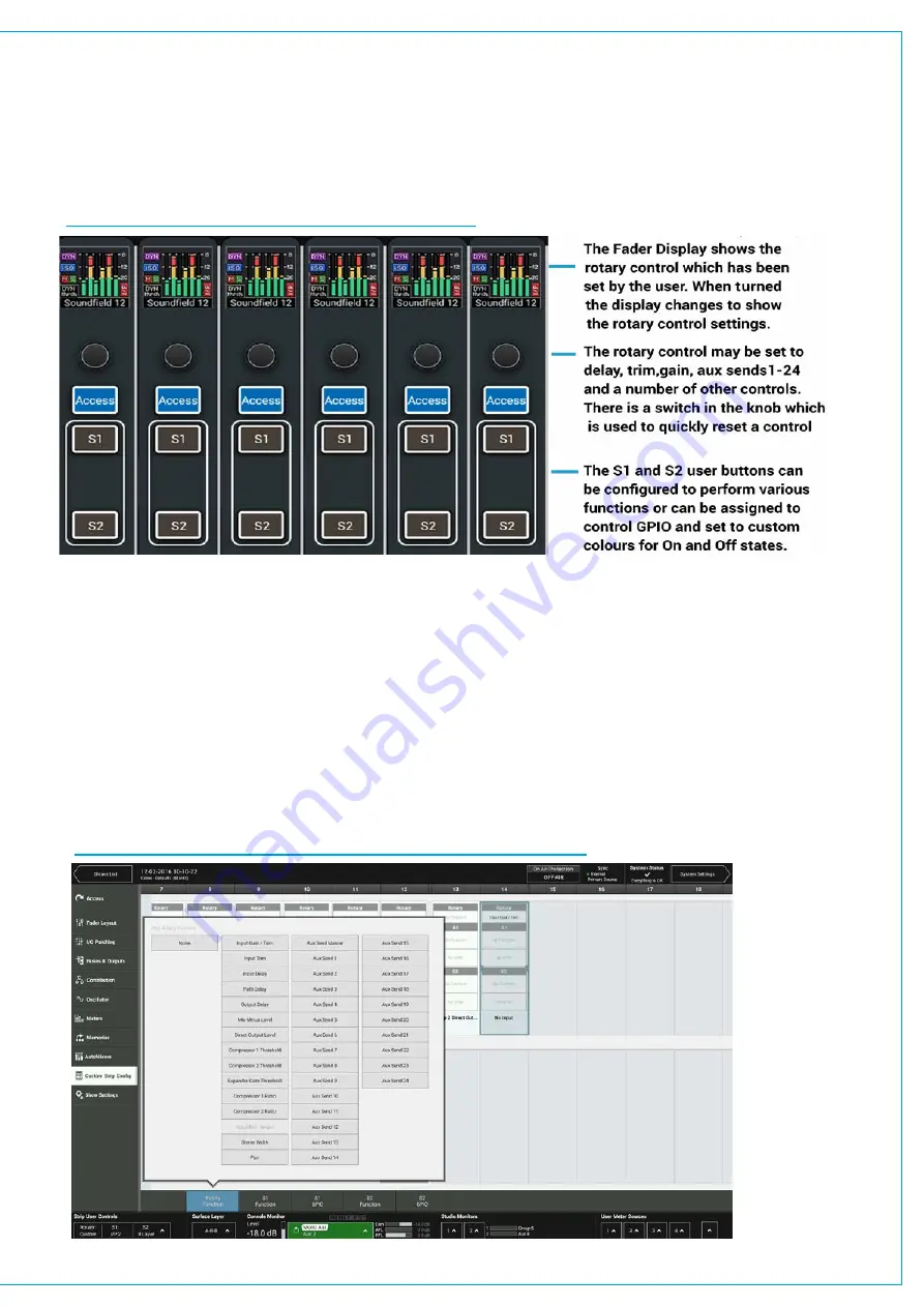
Each Fader strip has a Rotary control and 2 Strip User Buttons each of which have RGB LED indicators in them.
They can be assigned to directly control a range of functions console wide, using the button in the left side of the
touch UI’s footer. The ‘Custom’ option allocates functions defined by the Custom Strip Configuration screen which
allows for different functions on each strip as well as connecting with GPIO.
FIGURE 1 - FADER STRIP ROTARIES &
USER BUTTONS
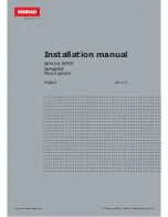
To create or change a Custom Strip Configuration, select the desired fader/s on screen, then choose to apply functions
using the Rotary, S1 or S2 buttons below.
GPIO can be assigned to the buttons as well as console functions. If a console function is assigned, the state of that
function will determine whether the button is lit. If no console function being controlled, the button can be lit by GPI tally,
and the illumination colour for both on and off state can be chosen. GPIO is connected to buttons via triggers. Select
a GPIO trigger to work with the S1 or S2 buttons from the footer. Go to the GPI and GPO patching screens in System
Settings to connect the specific GPI and or GPO to the user button triggers.
A separate Custom Strip Configuration is available to each user memory. The custom configuration is only active on
the surface when Custom is selected from the button in the bottom left of the UI footer. Users can choose to apply the
custom configuration to the rotary and/or each of the buttons independently.
FIGURE 2 - CUSTOM STRIP CONFIGURATION-ROTARY FUNCTIONS
Summary of Contents for BRIO 36
Page 1: ...calrec com Audio Production System with Optional Networking BRIO 36 USER MANUAL V1 1...
Page 12: ...12 BRIO 36 Audio Production System with Optional Networking...
Page 13: ...calrec com BRIO 36 PRODUCT INFORMATION...
Page 20: ...20 BRIO 36 Audio Production System with Optional Networking...
Page 21: ...calrec com BRIO 36 SYSTEM OVERVIEW...
Page 29: ...29 FIGURE 1 BRIO 36 USER INTERFACE DISPLAY...
Page 43: ...calrec com BRIO 36 SETTING UP...
Page 47: ...47 FIGURE 1 SYNCHRONISATION OPTIONS...
Page 67: ...calrec com BRIO 36 GETTING SIGNALS IN AND OUT...
Page 93: ...93 FIGURE 1 THE DIRECT OUTPUT SCREEN...
Page 100: ...100 BRIO 36 Audio Production System with Optional Networking...
Page 101: ...calrec com BRIO 36 PROCESSING...
Page 146: ...146 BRIO 36 Audio Production System with Optional Networking...
Page 147: ...calrec com BRIO 36 MONITORING...
Page 149: ...149 FIGURE 3 EXAMPLE LOUDSPEAKERS SETUP...
Page 155: ...calrec com BRIO 36 METERING...
Page 163: ...calrec com BRIO 36 COMMUNICATIONS...
Page 172: ...172 BRIO 36 Audio Production System with Optional Networking...
Page 173: ...calrec com BRIO 36 ROUTING...
Page 175: ...175 FIGURE 1 CONFIGURING BUSES AND OUTPUTS...
Page 182: ...182 BRIO 36 Audio Production System with Optional Networking...
Page 183: ...calrec com BRIO 36 EXTERNAL INTERFACING...
Page 193: ...calrec com BRIO 36 CONSOLE FACILITIES...
Page 198: ...198 BRIO 36 Audio Production System with Optional Networking...
Page 199: ...calrec com BRIO 36 TERMINOLOGY...
Page 207: ...calrec com BRIO 36 FEATURES BY SOFTWARE VERSION...


