Audio Production System with Optional Networking
F
ader Display
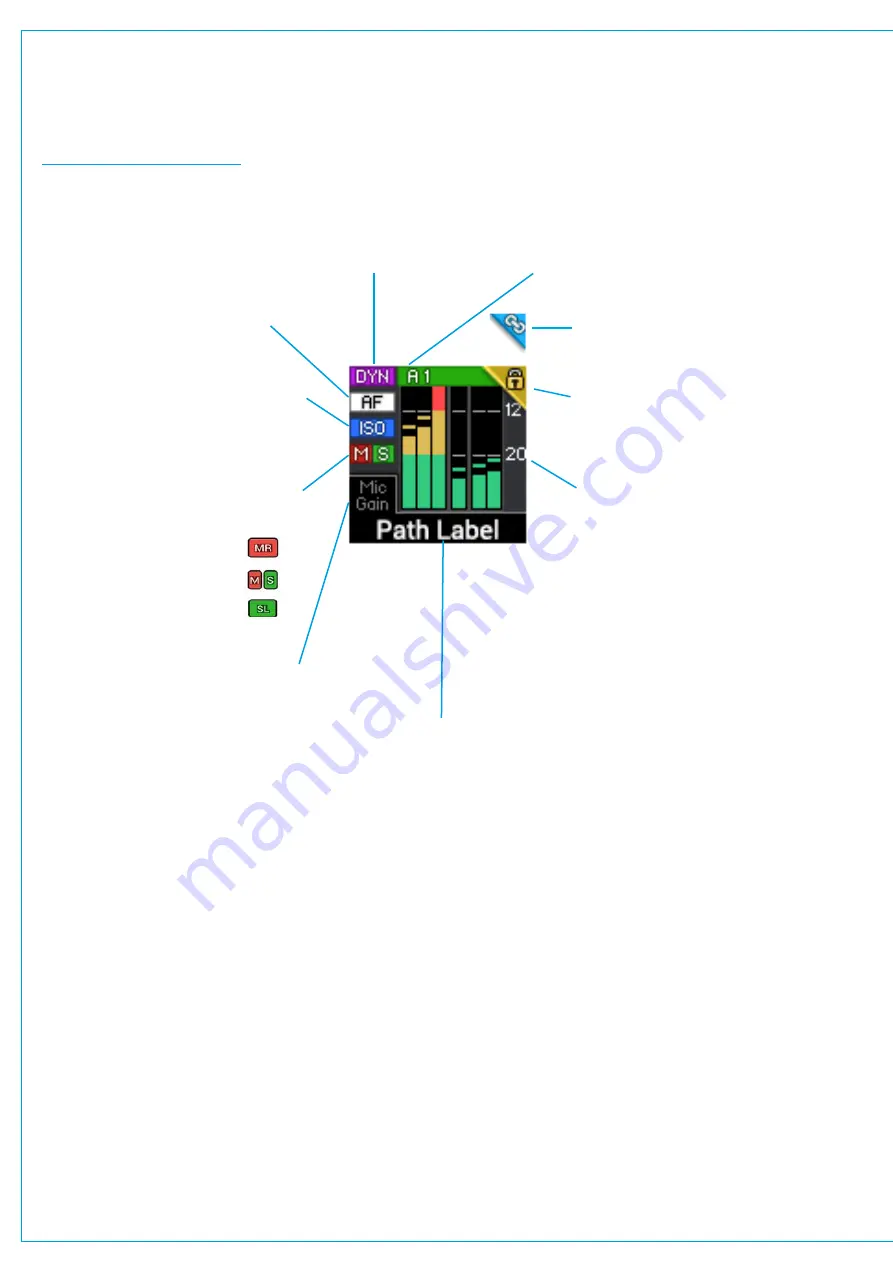
Each fader strip includes a small TFT display. Figure 2 shows highlights each icon which can appear on the display.
FIGURE 2 -
FADER DISPLAY
The lock symbol is displayed for a
short period on faders that are locked
to the surface when changing layers.
The link symbol is displayed in the
same space as the lock symbol if this
path is control linked with another.
The A1 or A2 shows that an AutoMixer is in
operation on this path. The brightness of the
coloured bar indicates the input ‘strength’ .
The DYN symbol shows that
there is a dynamics element
in circuit and active.
The AF symbol shows that there is an
AutoFader in circuit and active.
If any of the meter legs go into overload
the background of the meter display
turns
RED
until the level is back in range.
The ISO symbol is displayed if the path
has been isolated from changes made
by memory loads. The ISO icon will be
green if the path is partially isolated.
The VCA group status indicators show
whether a fader or path is a:-
Master
SubMaster
or Slave
The input meter is a small bar graph
which displays the path’s signal level
in Mono, Stereo or 5.1 Surround as
shown here Note when the signal
is off the bottom a label shows the
name of the leg. The position of the
scale markers and colour change
points, as well as PPM or VU ballistics
is selectable from System-Settings
General, under meter style.
The meter can be selected to display
input or post fader audio, per path
from the Meter and PFL button in the
Access view’s sub-header.
The Path label is either the native
label, or the H2O user label
generated within H2O or the
User label which can be edited
from the Brio surface.
If this area of the display is labelled
then it means that Path’s rotary control
has also been set up as a control cell.
See next page for examples.
The control label is always visible
if assigned and the control value is
displayed when the control is adjusted.
Summary of Contents for BRIO 36
Page 1: ...calrec com Audio Production System with Optional Networking BRIO 36 USER MANUAL V1 1...
Page 12: ...12 BRIO 36 Audio Production System with Optional Networking...
Page 13: ...calrec com BRIO 36 PRODUCT INFORMATION...
Page 20: ...20 BRIO 36 Audio Production System with Optional Networking...
Page 21: ...calrec com BRIO 36 SYSTEM OVERVIEW...
Page 29: ...29 FIGURE 1 BRIO 36 USER INTERFACE DISPLAY...
Page 43: ...calrec com BRIO 36 SETTING UP...
Page 47: ...47 FIGURE 1 SYNCHRONISATION OPTIONS...
Page 67: ...calrec com BRIO 36 GETTING SIGNALS IN AND OUT...
Page 93: ...93 FIGURE 1 THE DIRECT OUTPUT SCREEN...
Page 100: ...100 BRIO 36 Audio Production System with Optional Networking...
Page 101: ...calrec com BRIO 36 PROCESSING...
Page 146: ...146 BRIO 36 Audio Production System with Optional Networking...
Page 147: ...calrec com BRIO 36 MONITORING...
Page 149: ...149 FIGURE 3 EXAMPLE LOUDSPEAKERS SETUP...
Page 155: ...calrec com BRIO 36 METERING...
Page 163: ...calrec com BRIO 36 COMMUNICATIONS...
Page 172: ...172 BRIO 36 Audio Production System with Optional Networking...
Page 173: ...calrec com BRIO 36 ROUTING...
Page 175: ...175 FIGURE 1 CONFIGURING BUSES AND OUTPUTS...
Page 182: ...182 BRIO 36 Audio Production System with Optional Networking...
Page 183: ...calrec com BRIO 36 EXTERNAL INTERFACING...
Page 193: ...calrec com BRIO 36 CONSOLE FACILITIES...
Page 198: ...198 BRIO 36 Audio Production System with Optional Networking...
Page 199: ...calrec com BRIO 36 TERMINOLOGY...
Page 207: ...calrec com BRIO 36 FEATURES BY SOFTWARE VERSION...


