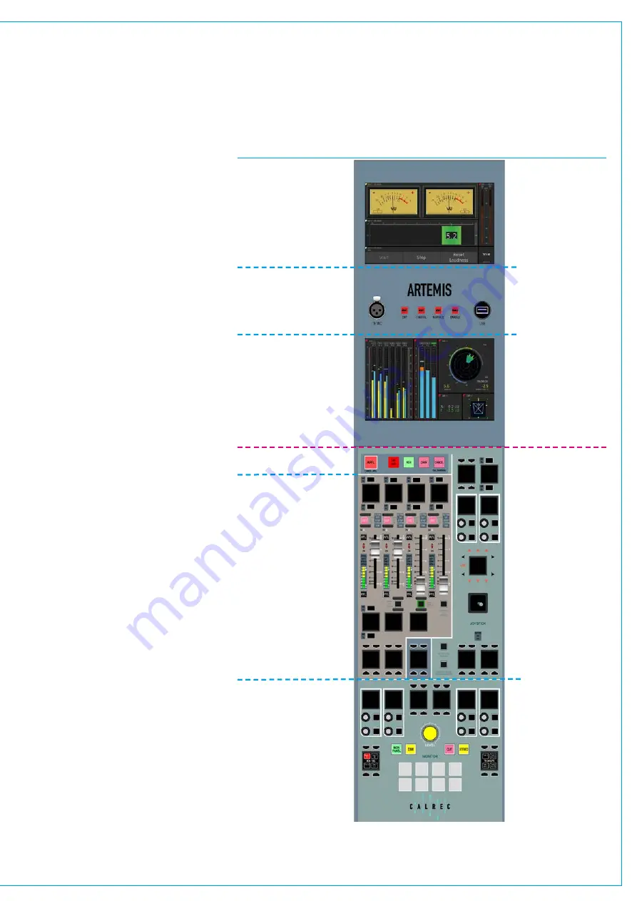
Monitor&Reset/OEMMeterpanels
In addition to the Fader Control and TFT
upstand Panels there is at least one set
of dedicated Monitor and Reset/3rd
Party Meter upstand Panels. An upstand
mounted reset/3rd party meter panel
is normally fitted above the dedicated
monitor panel. Several variants of this
panel are available with different metering
options.
Reset,TalkbackMicandUSBport.
The ability to reset the DSP, Surface
and/or Console Surface is provide on
the upstand panel and an enable button
is also provided to prevent accidental
operation. The Talkback Mic 3-pin XLR
socket provided can use any Mic I/P port
in the system. The USB port provided
allows the user to backup and restore
information to/from a Memory stick.
3rdpartymeters
Reset panels can be supplied with RTW
TM7s or DK MSD600
++
s. These are
powerful units made by specialist meter
manufacturers, offering visual surround
field representation with comprehensive
phase metering, alongside other
features such as loudness metering
and stereo vectorscopes. Please refer
to the manufacturer’s documentation
for full details of the full feature set and
configuration information. Reset panels
are also available without 3rd party meters
MonitorPanel
Monitor panels fit in the control bed and
provides a dedicated set of monitoring
controls.
As well as monitoring controls,
surround spill, surround downmix and
joystick panning, this panel also provides
On-Air / Rehearse condition
switching,
GPIO assignable button & LED tallies, as
well as talkback keys. See Fig 3.
If required, for example on a large
console or for multiple operators, multiple
monitor panels can be fitted. Each can
switch between controlling monitor 1
and monitor 2 as well as having access
to miscellaneous monitor/headphone
outputs.
See
“Dedicated Monitor Controls” on page
for details.
FIG 3 - MONITOR PANEL AND UPSTAND METER/RESET PANEL COMBINATION
Upstand
Control bed
Optional 3rd Party
Metering Unit
Reset, Talkback
Mic and USB port
Optional 3rd Party
Metering Unit
Broadcast Facilities
Spill Controls
Joystick Controls
Monitor Controls
Customer Switches
Summary of Contents for Artemis
Page 7: ...calrec com Putting Sound in the Picture ARTEMIS INFORMATION ...
Page 11: ...calrec com Putting Sound in the Picture ARTEMIS INTRODUCTION ...
Page 17: ...calrec com Putting Sound in the Picture ARTEMIS CONTROL OVERVIEW ...
Page 29: ...calrec com Putting Sound in the Picture ARTEMIS CONTROL PANEL MODES ...
Page 36: ...36 ARTEMIS Digital Broadcast Production Console Control Panel Modes WILDABLE CONTROLS ...
Page 39: ...calrec com Putting Sound in the Picture ARTEMIS GETTING SIGNALS INTO ARTEMIS ...
Page 69: ...calrec com Putting Sound in the Picture ARTEMIS PROCESSING AUDIO ...
Page 93: ...calrec com Putting Sound in the Picture ARTEMIS ROUTING AUDIO ...
Page 109: ...calrec com Putting Sound in the Picture ARTEMIS PASSING SIGNALS OUT OF ARTEMIS ...
Page 117: ...calrec com Putting Sound in the Picture ARTEMIS MONITORING ...
Page 132: ...132 ARTEMIS Digital Broadcast Production Console Monitoring ...
Page 133: ...calrec com Putting Sound in the Picture ARTEMIS COMMUNICATIONS ...
Page 138: ...138 ARTEMIS Digital Broadcast Production Console ...
Page 139: ...calrec com Putting Sound in the Picture ARTEMIS METERING ...
Page 148: ...148 ARTEMIS Digital Broadcast Production Console ...
Page 149: ...calrec com Putting Sound in the Picture ARTEMIS SHOWS MEMORIES AND PRESETS ...
Page 163: ...calrec com Putting Sound in the Picture ARTEMIS CONSOLE FACILITIES ...
Page 168: ...168 ARTEMIS Digital Broadcast Production Console ...
Page 169: ...calrec com Putting Sound in the Picture ARTEMIS EXTERNAL INTERFACING ...
Page 180: ...180 ARTEMIS Digital Broadcast Production Console External Interfacing ...
Page 181: ...calrec com Putting Sound in the Picture ARTEMIS SYSTEM STATUS ...
Page 184: ...184 ARTEMIS Digital Broadcast Production Console ...
Page 185: ...calrec com Putting Sound in the Picture ARTEMIS GLOSSARY OF TERMINOLOGY ...
Page 191: ...calrec com Putting Sound in the Picture ARTEMIS FEATURES BY SOFTWARE VERSION ...


