background image

GB

MXV, MXV-B Rev6 - Operating Instructions

Page 17 / 136

Provide space around the pump for motor 

ventilation, to allow for checking of shaft rotation, 

for filling and draining the pump and to allow for 

collection of the liquid to be removed

 (especially 

for draining liquids which are harmful or have to be 

removed at temperatures higher than 60 ˚C).


Make sure prolonged accidental leakage of 

liquid does not cause damage to persons 

or property.

Leakage may develop as a result of surge pressure or 

water hammer, erroneous operations (such as failing 

to close a plug or valve) or other functional disorders. 

Allow for the possibility of channeling away any leaked 

liquid or for an automatic drainage system against 

flooding.

Mount the pump on a flat horizontal surface (using a 

level gauge) such as a solid cement base or a rigid 

supporting structure in metal.

To ensure stability, insert, if necessary, small pieces of 

calibrated metal plate next to the 4 anchoring screws.

6.5.  

Connecting the motor (only MXV(L), 

MXV(L)4)

The 

MXV(L), MXV(L)4

 pumps are designed for use 

with  standard  electric  motors  with  (IEC  34-7)  IM  V1 

construction form and dimensions and output ratings 

in accordance with IEC 72.

If a pump is supplied without the motor

, check the 

rated power and rpm indicated on the name plate and 

technical data given in the data sheet.

ATTENTION

: the motors must have two lifting points 

in diametricalIy opposite positions for vertical lifting 

with the shaft end downwards (fig.1 b)

Before installation clean the motor shaft extension, the 

key and contact surfaces of the flanges to remove any 

protective paint, dirt or oxydation.
Lubricate  the  motor  shaft  extension  with  a  graphite-

base, dripfree, anti-friction product.

Do not use oil as it can harm the mechanical seal 

below (see 

section 8.4.

).

With the pump in the vertical position, insert the motor 

shaft in the coupling, aligning the key with the key slot 

and resting the motor flange on the lantern flange.

Turn the motor, adjusting the position of the terminal 

box as required and aligning the holes on the flanges.

ATTENTION

:  the  4  flange  screws  (70.18)  with 

nut must be uniformly tightened with alternated 

crossover tightening procedure in diametrically 

opposite positions (see 

section 9.1.

).

Before and after tightening the screws (70.18), make 

sure the coupling with pump shaft and motor shaft can 

be freely turned by hand (remove and then replace the 

guard 32.30).

ATTENTION

: for removing or replacing the motor 

see 

section 8.3.

6.6. Pipes

Provide a diameter assuring a liquid flow velocity not 

higher than 1.5 m/s for suction, and 3 m/s for delivery.

The  pipe  diameters  must  never  be  smaller  than  the 

pump connection ports.

The arrows on the pump casing (14.00) indicate the 

inlet (suction) and outlet (delivery) ports.

Ensure the internal pipe surface is clean before 

connection.

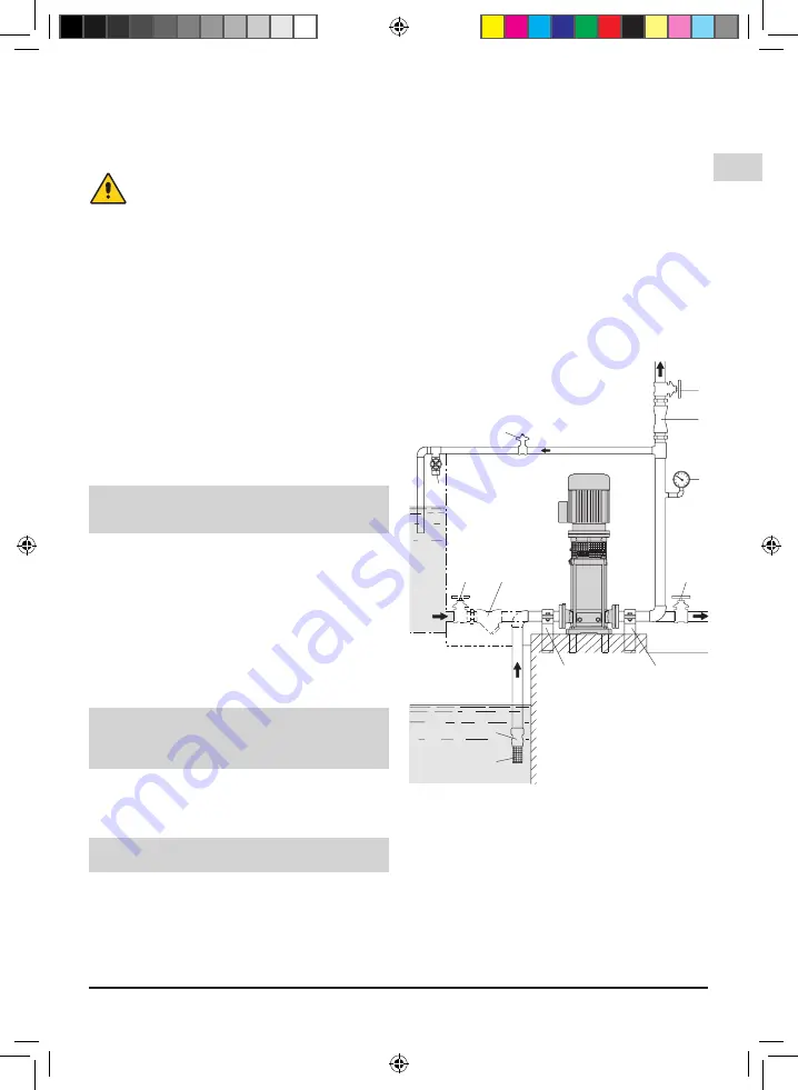
Secure all pipes to their rests close to the pump and 

connect them so that they are not subjected to stress 

and  do  not  transmit  vibration  or  flexion  strain  to  the 

pump (see  

fig.3

).

Provide for the possibility of draining the pump 

without having to drain the entire system.

Install  correctly  any  compensators  for  absorption  of 

expansion or impeding noise transmission.

Make sure gaskets do not protrude inside the pipes 

for  the  pump  types  MXV-B,  MXV(L)  25,32,40  and 

MXV(L)4  25,32,40  screw  the  union  couplings  or  the 

flanges into the 

threaded ports

 (ISO 228) by inserting 

in the joint a suitable sealing material.

Tighten the pipes or union couplings only to the extent 

sufficient to ensure a tight seal. Excessive torque may 

damage the pump.

With 

flanged  ports

 make sure the gaskets do not 

protrude inside the pipes.

A

B

6

3

5

2

7

4

5

7

1

5

1

5

3.93.113

6.6.1. Suction pipe

When  a 

pump is located above the water level


(suction lift operation, 

fig. 3 A

), fit a foot valve with a 

strainer, which must always remain immersed.

The suction pipe must be perfectly airtight and be led 

upwards in order to avoid air pockets.

When the 

liquid level on the suction side is above 

the pump

 (inflow under positive suction head, 

fig. 3 

B

), fit a gate valve.

Follow  local  specifications  if  increasing  network 

pressure.

Install a strainer on the suction side of the pump to 

prevent foreign particles from entering the pump.

1. Strainer

2. Foot valve

3. Check valve

4. Bypass valve

5. Gate valve

6. Pressure gauge

7. Supports and clamps for 

    pipelines

Fig. 3  Systems diagram


A = Suction lift operation


B = Positive suction head operation

MXV, MXV-B Rev6.indd   17

01/10/18   17:06

Summary of Contents for MXV-B Series

Page 1: ...pump Verticale meertraps in line pompen in line MXV B MXV L MXV L 4 ISTRUZIONI ORIGINALI PER L USO Pagina 2 Italiano OPERATING INSTRUCTIONS Page 14 English BETRIEBSANLEITUNG Seite 26 Deutsch INSTRUCT...

Page 2: ...the understanding of the manual below are indicated the symbols used with the related meaning Information and warnings that must be observed otherwise there is a risk that the machine could damage or...

Page 3: ...ng The following picture is a copy of the name plate that is on the external case of the pump 1 Type 1 2 Delivery 3 Head 4 Rated power 5 Supply voltage 6 Fr quence 7 Nom motor current 8 Rotation speed...

Page 4: ...les must comply for the weight and dimensions with the chosen product see technical catalogue dimensions and weights 5 1 Handling Handle with care the packages must not receive impacts Avoid to impact...

Page 5: ...ightened with alternated crossover tightening procedure in diametrically opposite positions see section 9 1 Before and after tightening the screws 70 18 make sure the coupling with pump shaft and moto...

Page 6: ...on device with curve D appropriate for the rated current of the pump Single phase MXV BM are supplied with a capacitor connected to the terminals and for 220 240 V 50 Hz with an incorporated thermal p...

Page 7: ...operation on the suction side 2 make sure all the suction pipe couplings are perfectly sealed and tighten the air vent plug 2 and the draining plugs 3 on the suction side fig 4 ATTENTION when the pump...

Page 8: ...has to be dismantled and cleaned Disconnect electrical power before any servicing operation and make sure the pump cannot be accidentally switched on 8 2 Dismantling the system Close the suction and...

Page 9: ...42 12 remove the sleeve seal jacket 42 10 the washer 42 14 so remove the stationary face of mechanical seal from the the cover plate for seal 42 00 Insert the stationary face of mechanical seal into...

Page 10: ...ialized company Make sure the specialized company follows the classification of the material parts for the separation Observe the local regulations and dispose the device accordingly with the internat...

Page 11: ...ee point 2a also 4 Insufficient flow 4a Pipes and accessories with diameter too small causing excessive loss of head 4b Presence of deposits or solid bodies in the internal passages of the rotor 4c Ro...

Page 12: ...catalogues 3 3 Machines with condensate discharge tap Make sure the discharge holes and taps are turned downwards All the discharge holes must be closed in dusty areas If there are condensation drain...

Page 13: ...that appears between the motor terminals even when the motor itself has stopped A motor with frequency converter can be powered even with the motor stopped 6 1 General inspection 1 Inspect the motor...

Page 14: ...ontaje Ritning f r demontering och montering Onderdelentekening 61 04 14 20 20 00 25 05 36 51 61 02 28 00 25 02 25 03 25 01 14 54 16 00 34 01 14 12 34 02 14 06 14 04 36 00 36 52 64 15 64 19 64 10 22 1...

Page 15: ...emontering och montering Onderdelentekening 1 14 16 14 19 14 18 14 17 66 18 99 00 70 18 70 19 3 66 18 66 19 66 00 28 04 14 02 61 00 14 20 28 08 22 12 13 60 64 10 64 19 64 15 64 00 36 52 36 00 14 04 14...

Page 16: ...0 34 09 32 04 42 00 42 10 36 00 36 52 36 51 28 00 25 02 13 60 64 15 64 14 28 04 14 12 14 17 14 18 14 19 70 19 70 18 32 70 66 00 32 74 61 04 34 08 14 20 34 02 32 24 42 04 42 12 42 14 14 02 34 01 14 48...

Page 17: ...94 055 4 INSERITO NEL CORPO STADIO 5 SOLO CON POMPE 65 32 6 NON PRESENTE NEI MOTORI 100 112 NON FORNIBILE SINGOLARMENTE 61 00 14 12 14 12 14 00 25 01 14 20 14 42 28 04 14 02 14 54 64 00 14 20 14 04 3...

Page 18: ...e Dibujo para desmontaje y montaje Ritning f r demontering och montering Onderdelentekening 70 18 66 00 32 30 32 32 64 25 64 24 32 04 36 00 14 20 28 00 25 02 14 54 28 24 30 00 51 01 51 04 25 03 25 01...

Page 19: ...sin canal de retorno Corpo primo stadio senza canale di ritorno First stage casing without return channel Stufengeh use erste Stufe ohne R ckf hrkanal Corps premier etage sans canal de retour 25 01 Co...

Page 20: ...Corps dernier tage sans bague d usure Stufengeh use letzte Stufe ohne Spaltring Corpo ultimo stadio senza anello di tenuta Last stage casing without wear ring Mellandel f rsta steget utan returkanal...

Page 21: ...Girante Impeller 25 05 Mellandel sista steget utan slitring Cuerpo ultimo elemento sin anillo cierre Corps dernier tage sans bague d usure Stufengeh use letzte Stufe ohne Spaltring Corpo ultimo stadio...

Page 22: ...tufengeh use mit Lager Corps d tage avec coussinet Cuerpo elemento con cojinete Mellandel med lager 25 03 Mellandel med returkanal Cuerpo elemento con canal de retorno Corps d tage avec canal de retou...

Page 23: ...uscinetto Stage casing with bearing Stufengeh use mit Lager Corps d tage avec coussinet Cuerpo elemento con cojinete Mellandel med lager 25 03 Mellandel med returkanal Cuerpo elemento con canal de ret...

Page 24: ...nsetzung Composition des tages roues et entretoises Composici n elementos rodetes y distanciadores Mellandelarnas pumphjulen och slitringarnas sammans ttning Trappen waaiers en bussensamenstelling Cor...

Page 25: ...132 136 MXV MXV B Rev6 New Old 2 4 1 3 5 6 MXV L 100 MXV MXV B Rev6 indd 132 01 10 18 17 07...

Page 26: ...MXV MXV B Rev6 133 136 M12 50 Nm Old New M8 20 Nm 8 10 12 7 9 11 MXV L 100 MXV MXV B Rev6 indd 133 01 10 18 17 08...

Page 27: ...appliance Bemessungsstrom des Ger tes Dimensiestroom van apparaat Sezione nominale Nominal cross sectional area Nennquerschnitt Nominale dwarsdoorsnede 3 6 10 16 25 32 40 0 75 1 0 1 5 2 5 4 6 10 6 10...

Reviews: