23
Appendix G - Installation Directions
The Whozz Calling? POS is designed to collect call data from standard analog central office telephone lines. It will
not work properly when connected to extensions (or station) lines coming from a telephone switch. Connect the
unit only to analog phone lines or phone lines that have been converted to analog signaling (i.e. Cable box
converters, analog terminal adaptors, etc.).
If your unit connects to a computer through a serial port, the serial port must be functioning correctly and no other
software application can be accessing this port. This unit will work with any serial port or COM number setting that
your software supports. If you do not have an available serial port on your computer, a USB-to-serial adaptor cable
can be used. These can be found at any computer store or most office supply outlets. This unit will work properly
with any USB-to-serial adaptor cable that is verified as, “correctly installed and operational” within the Windows
device Manager
If you unit connects via Ethernet cable, plug it into any switch or router on your Local Area Network. Use the
Ethernet Configuration Tool located at
www.CallerID.com/downloads/diagnostic-tools/
to set the unit to a static IP
address within your IP scheme and outside any DHCP range. Refer to the Ethernet Supplement for more details.
Connecting To Phone Lines
There are two basic methods of connecting the monitoring unit to your phone lines: the series (pass through)
connection, or the parallel (branch off) connection. The series connection uses both input and output modular jacks
on the unit. The parallel connection uses only the input jacks.
Parallel Connection (recommended)
A parallel phone line connection is recommended and often easier since the incoming lines to the building can
simply be "branched off" to the unit. This connection allows the unit to be removed from service for
troubleshooting or repair without affecting the telephone call path. With this connection only the input ports on the
unit are used.
Figures G2a & G2b show parallel connections. This involves branching off or "tapping" from each phone line to be
monitored and connecting them to their respective input jacks on the unit. If appropriate, bare wire to modular
adapters may be required.
Series Connection
Connecting the unit in series with the telephone lines is required only in special circumstances. Only if you need to
operate the unit in a loop current detection mode, require first ring suppression, or are using call blocking would the
unit need to be wired in series. with the telephone lines. If the unit is connected in series and then taken out of
service, the input and output phone lines have to be connected together to resume normal telephone call flow.
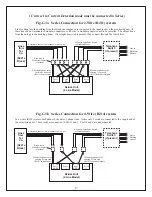
Figures G3a & G3b show series connections. Each phone line to be monitored passes through the unit. Phone lines
coming into the building connect to the input jacks on the unit (through bare wire to modular adapters, if needed).
Lines connected to the output jacks continue to the desktop phones (through a phone switch, if present).


