


S320 OCS Hardware User Guide
Doc. Part No. 460167-00
May 27, 2015
Rev. B7
Page 21 of 46
Light is directed from the input fibers to the output fibers using arrays of microscopic silicon
mirrors that are fabricated using the proven MEMS process. An optical signal transmitted
through the S320 OCS passes through three sections of the MSM: the input collimator array,
which directs the light from each input fiber to its input mirror; the mirror matrix, an array of
MEMS input mirrors and an array of MEMS output mirrors; and the output collimator array,
which couples light from each output mirror back into its output fiber. High-quality mirrors and
collimators, coupled with precise electrostatic control of the position of each mirror, enable
switch times of less than 20 ms and optical loss that is typically less than 2.0 dB.
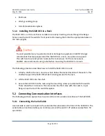
The MSM shown in Figure 3 is the core of the S320 OCS system. The MSM supports up to 320
input fiber terminations and up to 320 output fiber terminations. It is controlled by the CPs and
powered by the Mirror Driver.
Figure 3 – MSM Block Diagram
The switching matrix in the MSM consists of a dedicated MEMS mirror for each input fiber
and a dedicated MEMS mirror for each output fiber. The angular position of each mirror is
determined by the voltages applied to the mirror by the mirror drivers. To direct light from an


