Calian SatService sat-nms LFTRX User Manual Download Page 5

1.1.1.1 EMC compliance

This equipment has been tested and meets the specification of following EMC standards:

EN 55032
EN 55024
FCC, part 15B
ICES003 To meet all EMC requirements it is necessary to keep with the cabling requirements
mentioned in the installation chapter.

1.1.1.2 Federal Communications Commission (FCC)

This equipment has been tested and found to comply with the limits for a Class B digital device,
pursuant to Part 15 of the FCC rules. These limits are designed to provide reasonable protection
against harmful interference in a residential installation.

This equipment generates, uses and can radiate radio frequency energy and, if not installed and
used in accordance with the instructions, may cause harmful interference to radio
communications. Operation of this equipment in a residential area is likely to cause harmful
interference; in which case, users are required to correct the interference at their own expense.

Note: To ensure compliance, properly shielded cables for data, I/O and RF connections shall be
used. Use double shielded twisted pair cables for I/O connections. We recommend to use CAT7
S/FTP cable, e.g. DRAKA UC900 SS27 Cat.7 PUR. These cables have to be shielded from end to
end, ensuring a continuous shield.

For RF connections use double shielded coaxial cable like e.g. RG223.

1.1.2 Safety compliance

This equipment has been tested and meets the specification of following safety standards:

EN 62368 Every single delivered unit is tested according to EN 60950 to ensure best
possible user safety.

To meet all safety requirements it is necessary to keep with the cabling requirements mentioned
in the installation chapter.

2 Installation

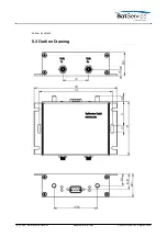
This chapter describes how to install the sat-nms LFTRX Fibre Optical Link. You find a guide how
to connect, configure and mechanically mount the equipment below.

Before you start, please first read the 

Safety Instructions

 chapter below. It contains some

important recommendations to prevent damage from the equipment.

2.1 Safety Instructions

Failure to observe all Warnings and Cautions may result in personnel injury and/or equipment
damage not covered by the warranty.

The equipment described in this manual is designed to be installed and used by
properly trained personnel only!

(C) 2021, SatService GmbH

www.satnms.com

LFTRX-UM-2107 Page 4/12

Summary of Contents for SatService sat-nms LFTRX

Page 1: ...at nms LFTRX User Manual Version 2 0 005 Copyright SatService Gesellschaft f r Kommunikationssysteme mbH Hardstrasse 9 D 78256 Steisslingen satnms support satservicegmbh de www satnms com www satservi...

Page 2: ...structions for optical connectors 6 2 3 Mechanical installation 6 2 4 Connecting the sat nms LFTRX 7 2 4 1 DC and data connector 8 2 4 2 RF connectors 8 2 4 3 Optical connectors 8 2 5 Line up the Opti...

Page 3: ...t or sub system Table Of Contents 1 Introduction 1 1 Compliances 1 1 1 CE Compliances 1 1 1 1 EMC compliance 1 1 1 2 Federal Communications Commission FCC 1 1 2 Safety compliance 2 Installation 2 1 Sa...

Page 4: ...the sat nms LFTRX user interface and elaborately describes the meaning of each alterable parameter Remote Control The sat nms LFTRX provides a versatile remote control interface A monitoring control s...

Page 5: ...isted pair cables for I O connections We recommend to use CAT7 S FTP cable e g DRAKA UC900 SS27 Cat 7 PUR These cables have to be shielded from end to end ensuring a continuous shield For RF connectio...

Page 6: ...quipment Take standard safety precautions with hand and or power tools When connecting the units fault relay circuits observe the maximum ratings 24V D C 50mA 2 2 Handling instructions for optical con...

Page 7: ...develop a suitable solution When planning the mechanical installation of the chassis please consider that the connectors are placed at the front and the backside of the enclosure Depending on the flex...

Page 8: ...d data connectors of the sat nms LFTRX chassis are located at the front side of the enclosure up right The figure below illustrates the location of the connectors and the pin out To meet mentioned EMC...

Page 9: ...adiation If connected to a power supply the sat nms LFTRX provides invisible laser radiation The source is class 3R Laser diode as defined in DIN EN 60825 1 2001 11 P0 2mW Lambda 1310nm Never look int...

Page 10: ...s 5 1 Frequency bands While the fibre optical links where designed by SatService GmbH mainly for the transmission of the satellite L Band frequency band 950 to 2150MHz also a broadband version from 50...

Page 11: ...Suhner by default 5 3 Outline Drawing C 2021 SatService GmbH www satnms com LFTRX UM 2107 Page 10 12...

Page 12: ...50 to 2150MHz or 10MHz only L Band Input Connectors Transmitter SMA female 50Ohm Input Return Loss 18dB L Band Output Connector Receiver SMA female 50Ohm Output Return Loss 18dB Optical connectors FC...

Page 13: ...Level per Carrier 45dBc 1500MHz M C Interface Specification Summary Fault and Monitoring Interface D SUB 9 pin Connector Electrical and Mechanical Specification Environmental Conditions Temperature ra...

Reviews: