background image

U

SER’S 

G

UIDE

 — 11

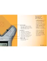
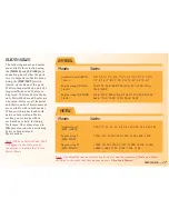
[ON/CLEAR]

Turns the unit ON and clears
the display. Holding down the
[ON/CLEAR]

 key for 1.5 seconds 

also powers the unit off.

[CLOSE +]

Completes the polygon 
and displays the calculated 
area. Results are identified 
as positive values. When 
measuring a polygon, this key 
connects the last measured 
point to the start point.

[MEASURE]

Takes a measurement 
between points.

Important Notes 
regarding the
[ON/CLEAR] key:

If [ON/CLEAR] is pressed 
during measurement, 
the last measured point 
is undone and the 
previous measurement is 
displayed. A second press 
of [ON/CLEAR] ends the 
measurement (as if the 
[END]

 key was pressed)

and clears the main display.

Additionally, if an error 
message is displayed 
during a measurement, 
pressing [ON/CLEAR] 
clears the error message 
and displays the previous 
measurement.

Summary of Contents for Ultra Scale Master 6250

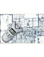
Page 1: ...USER S GUIDE Digital Area Take Off Tool Model 6250...

Page 2: ...ffs for all fields of construction Use it for estimating project materials and costs for measuring storing and calculating perimeters areas and volumes from architectural plans and other types of scal...

Page 3: ......

Page 4: ...ES 17 SHAPES AND DEFINITIONS 18 MEASURING POLYLINES 19 MEASURING SIMPLE POLYGONS 20 MEASURING TAKE OUTS 21 MEASURING COMPLEX POLYGONS 23 MEASURING IRREGULAR SHAPES 24 CUSTOM SCALES 25 SETTING A MEASUR...

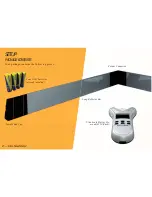
Page 5: ...SCALE MASTER Ultra Scale Master Pro model 6250 Puck SETUP PACKAGE CONTENTS Your package contains the following pieces Female End Cap Corner Connector Long Reflector Bar Four AAA batteries already ins...

Page 6: ...USER S GUIDE 3 Male End Cap Short Reflector Bar Long Reflector Bar Carrying Case User s Guide Quick Reference Guide and Quick Setup Sheet...

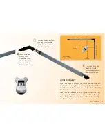
Page 7: ...of the first Long Reflector Bar The Female End Cap is preinstalled for a Right Hand configuration 1 Insert the male end of the Corner Connector into the female end of the first Long Reflector Bar 2 In...

Page 8: ...L ASSEMBLY The ultrasonic beams are sent from the left arm of the Puck to the top bar then reflected back and from the right arm of the Puck to the side bar then reflected back as shown above The Puck...

Page 9: ...nd of the second Long Reflector Bar into the female end of the Short Reflector Bar 3 4 Insert the male end of the Short Reflector Bar into the Female Bar End Cap 4 LEFT HAND ASSEMBLY Assemble the refl...

Page 10: ...ns parallel to the top bar and the left arm remains parallel to the side bar as shown above 1 Insert the male end of the first Long Reflector Bar into the female end of the Corner Connector 1 1 Insert...

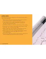
Page 11: ...The Puck should maintain a 45 angle within the bars while measuring 4 Ensure that the measuring surface is flat and smooth Make sure there are no folds tears or raised areas of the plans 5 Make sure...

Page 12: ...Right Hand Configuration Shown USER S GUIDE 9...

Page 13: ...s the polygon and displays the calculated area Results are identified as negative values When measuring a polygon this key connects the last measured point to the start point KEY DEFINITIONS MEASURING...

Page 14: ...measured point to the start point MEASURE Takes a measurement between points Important Notes regarding the ON CLEAR key If ON CLEAR is pressed during measurement the last measured point is undone and...

Page 15: ...surements upon repeated presses of UNDO SET Used in conjunction with the SCALE key to set a custom scale see Custom Scales section Also used to access secondary functions e g M MC AREA Displays the ca...

Page 16: ...third consecutive press displays the memory average Repeated presses cycle back through the list of values 4RIGHT ARROW Used to move through the digits while setting a custom scale see Custom Scales...

Page 17: ...within each mode see Built in Scales section SET SCALE Used to move back through the list of available scales RESET Clears all values and resets all settings including preferences to their factory de...

Page 18: ...UNITS Used to select from the list of available units of measurement see Units of Measurement section SET UNITS Used to move back through the list of available units of measurement USER S GUIDE 15...

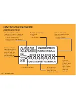
Page 19: ...to display values and important messages Unit Legend is a descriptions of displayed values i e Square Feet Inch USING THE ULTRA SCALE MASTER UNDERSTANDING THE LCD Low Battery Indicator The area immedi...

Page 20: ...Metric Mode MET will appear in the scale area of the display to indicate that it is in Metric Mode IMPERIAL Modes Scales Architectural ARCH 1 Foot Engineering I ENGI 1 Inch Engineering II ENGII 1 Inch...

Page 21: ...the User s Guide POLYLINE A sequence of connected straight lines or a single linear distance like a fence line POLYGON A closed geometric figure bounded by three or more straight lines 1 Simple Polyg...

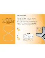
Page 22: ...l show the Length of the 1st line segment 3 Move to the third point and press the MEASURE key The display will show the accumulated Length of the two measured segments PERIMETER 4 Press the END key Th...

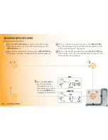
Page 23: ...e first line segment 3 Move to the third point and press the MEASURE key The display will show the accumulated Length of the two measured segments 4 Move to the fourth point and press the MEASURE key...

Page 24: ...int and press the MEASURE key The display will show the Length of the first line segment 3 Move to the third point and press the MEASURE key The display will show the accumulated Length of the two mea...

Page 25: ...he M key to store the Area in Memory then repeat steps 1 through 4 for the Take Out 5 7 Press the CLOSE key followed by the SET then M keys Now press the MR key to display the Adjusted Area Press the...

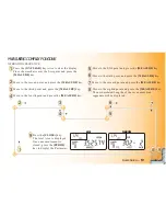
Page 26: ...e fourth point and press the MEASURE key 5 Move to the fifth point and press the MEASURE key 6 Move to the sixth point and press the MEASURE key 7 Move to the seventh point and press the MEASURE key 8...

Page 27: ...press the MEASURE key 5 Move to the fifth point and press the MEASURE key 6 Move to the sixth point and press the MEASURE key 7 Move to the seventh point and press the MEASURE key 8 Move to the eighth...

Page 28: ...place or until an All Clear or Reset is performed Switching between Imperial and Metric Modes does not clear stored Custom Scales SETTING A MEASURED CUSTOM SCALE CUSTOM SCALES 1 Press MODE until CUST...

Page 29: ...through the digits 7 Use AREA 5or PERIM 6to increase or decrease the selected digit 8 To store the Custom Scale press SET or SCALE To confirm the scale has been set Scl Set is displayed for one secon...

Page 30: ...ntry mode The selected digit begins flashing indicating that it is ready to be changed Use MR 4to move through the digits 5 Use AREA 5or PERIM 6to increase or decrease the selected digit 6 To store th...

Page 31: ...al and Metric modes and are displayed in the order shown beginning with the default The Imperial Metric switch located on the back of the puck determines the default starting unit Note You may change...

Page 32: ...on error usually occurs when attempting to store values of different dimensions into Memory OFLO Overflow value is too large to be displayed SEnd Error Not connected to a PC Auto Shut off The Ultra Sc...

Page 33: ...nd a Return Merchandise Authorization RMA Call Toll Free 1 800 854 8075 Outside USA 1 775 885 4900 www calculated com warranty WARRANTY Warranty Repair Service U S A Calculated Industries CI warrants...

Page 34: ...freight and duties Disclaimer CI MAKES NO WARRANTY OR REPRESENTATION EITHER EXPRESS OR IMPLIED WITH RESPECT TO THE PRODUCT S QUALITY PERFORMANCE MERCHANTABILITY OR FITNESS FOR A PARTICULAR PURPOSE AS...

Page 35: ...ated Industries Inc 2007 Ultra Scale Master and Calculated Industries are registered trademarks of Calculated Industries Inc ALL RIGHTS RESERVED CALCULATED INDUSTRIES 4840 Hytech Drive Carson City NV...

Reviews: