


10/12/13
LMU-3xx Hardware & Installation Guide - PULS Wiki
https://puls.calamp.com/wiki/LMU-3xx_Hardware_%26_Installation_Guide
24/37
The RF cables which are provided for connecting to the LMU antennas should be used at the length provided.
Do not cut cables. Instead, coil any excess cable length, making sure not to crimp or flatten the antenna cable.
5.2.7 Moisture and Weather Protection
The LMU unit must be located where it will not be exposed to moisture or water. In a typical installation inside
a vehicle this is not commonly thought to be a concern; however, it might be best to avoid locating the LMU
below a car’s cup holders, or where rain might easily splash into the compartment when a door is opened.
5.2.8 Preventing Accidental or Unauthorized Modification
If you anticipate that fleet drivers or others might interfere with the LMUs once they are installed, take steps to
be sure that it is not easy to disconnect the antenna wiring, remove the LMU from its power source, etc.
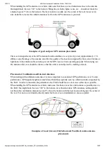
Two common methods are the use of Tamper Proof Sealant or creation of PEG Script to detect power loss or
GPS antenna disconnections.
5.3 Installing the LMU in a Vehicle
This section provides instructions for installing an LMU in a vehicle.
Be sure to consider the design decisions described in the previous sections. When you are ready to begin
installing the LMU, follow these steps:
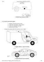
5.3.1 Place the LMU unit in the vehicle.
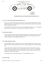
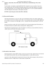
Typically, the LMU should be placed under the passenger seat or dashboard of the vehicle. LMUs with
internal antennas should be placed to maximize their GPS performance. A typical location include under the
dash close to the front wind-shield.
Attach the LMU to the solid body of the vehicle, not to plastic panels. The LMU can be placed out of sight by
removing interior trim and molding to expose available space, then replacing the trim once the LMU is in place.
5.3.2 Connect power, ignition, and ground.
The power input (red wire) must be connected to a constant (un-switched) +12 VDC or +24 VDC supply;
preferably, connected directly to the vehicle battery terminal or as close to it as possible. This connection point
should be fuse protected to not more than 5 Amps.
The ignition input (white wire) must be connected to the vehicle ignition or another appropriate key operated
line, such as ACCESSORY, ensuring that power to the ignition wire is available only when the vehicle ignition
is on.
The ground line (black wire) must be connected to chassis ground.


