background image

GRACE3 - SPIRIT3 - MADISON - TABLA - ROXY - ATRIUM - SOLO 5

8

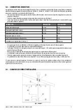
LEGEND

Fig. 6

1

Insulating material

2

Reduction from Ø100 to Ø80 mm

3

Inspection plug 

4

Minimum safety distance = 0,5 mt

•  Chimney flue installation Ø100/120 mm with an enlarged drilling for pipe transit.

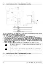
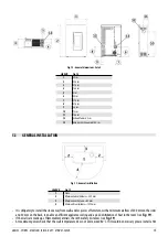
Fig. 7 - Example 2

LEGEND

Fig. 7

1

Insulating material

2

Inspection plug

3

Chimney inspection entrance

4

Minimum safety distance = 0,5 mt

5

Inclination ≥ 3°

6

Level section ≤ 1 mt

•  Old chimney flue with an inserted pipe of minimum Ø100/120 mm and with an external door which enables the chimney 

cleaning.

Fig. 8 - Example 3

Summary of Contents for ATRIUM

Page 1: ...EN 2019CADELsrl Allrightsreserved Tuttiidirittiriservati GRACE3 SPIRIT3 MADISON TABLA ROXY ATRIUM SOLO 5 INSTALLER MANUAL Pellet Stove ...

Page 2: ...LLATION 15 5 4 STOVE DOOR REMOVAL INSTALLATION 16 5 5 GRACE3 FRAME ASSEMBLING 16 5 6 FRAME DISASSEMBLY SPIRIT3 MADISON SOLO 5 TABLA 19 5 7 ROXY ATRIUM PANEL DISASSEMBLY 19 5 8 UPPER EXHAUST GRACE3 20 5 9 ASSEMBLY OF THE GRACE PEDESTAL 3 OPTIONAL AND ROXY STAND 21 5 10 GRACE3 WALL MOUNTING OPTIONAL 21 5 11 ELECTRIC CONNECTION 23 5 12 CONNECTION TO THE EXTERNAL THERMOSTAT ATRIUM ROXY MADISON TABLA S...

Page 3: ... ones in accordance with current regulations After having removed the packaging please assure you about the integrity of the product 2 2 STOVE HANDLING Both whether the stove is packed or not it is necessary to observe the following instructions for handling and transporting the stove from its sale point to its installation point and for any future movements The stove must be handled with idoneous...

Page 4: ... importance for the correct running of the heating appliance It is fundamental that the chimney flue is perfectly built and always maintained with a perfect efficiency Thechimneyfluemustbesole seeFig 1 withinsulatedstainless steelpipes 1 orinstalledontheexistingchimneyflue 2 Both this solutions must be endowed with an inspection plug 3 and or an inspection door 4 3 3 TECHNICAL FEATURES Fig 2 Incli...

Page 5: ...dimension must be minimun Ø100 mm recommended max Ø180 mm Made the efficiency of the chimney flue overhauled by an expert stove repairer and if necessary cover the chimney flue with materials in compliance with current regulations The flue system must be placed on the roof The chimney flue must be provided CE in accordance with EN 1443 regulation Please find attached an example of label Fig 3 Exam...

Page 6: ...idth and fitted in a way that the fume exhaust is assured also in case of wind It should prevent the infiltration of rain snow and animals The outlet height in the atmosphere must be away from the reflux area caused by the roof structure or by obstacles laying nearby see Fig 2 3 7 CHIMNEY COMPONENTS Fig 5 Chimneycomponents LEGEND Fig 5 1 Chimneypot 2 Fumeoutlet 3 Chimneyflue 4 Termalinsulation 5 E...

Page 7: ... 2 mt 2 mt Installation at a height above 1200 m a s l NO Obligatory Use a plate pipe for stoves of Ø80 mm or Ø100 mm depending on the type of system and with silicone gaskets It is forbidden to use metal fibre cement or aluminium flexible pipes For change of direction it is obligatory always to use a union with angle 90 with inspection plug which enables an easy periodic cleaning of the pipes Ple...

Page 8: ...lue installation Ø100 120 mm with an enlarged drilling for pipe transit Fig 7 Example2 LEGEND Fig 7 1 Insulatingmaterial 2 Inspectionplug 3 Chimneyinspectionentrance 4 Minimumsafetydistance 0 5mt 5 Inclination 3 6 Levelsection 1mt Old chimney flue with an inserted pipe of minimum Ø100 120 mm and with an external door which enables the chimney cleaning Fig 8 Example3 ...

Page 9: ...ntilate 2 Externalairinlet The room must be endowed with an external air recycling for a good climate in your ambient The air inflow from outside to the inner occurs directly through an opening on the external wall of the room see Fig 9 Bedrooms garages and store of flammable materials are excluded The air inlet should have a total net surface of 80 sqcm2 the aforesaid surface is to widen if insid...

Page 10: ...avity During installation step is necessary to verify the minimum distances required for the combustible air inlet as for example an opendoororwindowcausesavortexwhichcouldremovethecombustibleairnecessarytothestove seetheunderlyingscheme On the external wall it is necessary to install a curve at 90 to protect the combustible air inflow from wind effects turn the curve inlet downwards see Fig 10 En...

Page 11: ...robable presence of other stoves or appliances which could depress the room Check at switched on stove if there is the presence of CO in the room Check if the chimney has the necessary draught Check if during the fume passage all has been executed in safety probable fume losses and distances from flammable mate rials etc The installation of the appliance must enable an easy access for appliance fu...

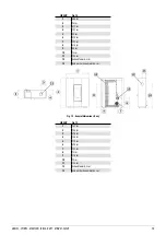
Page 12: ...31 5cm 9 6 6cm 10 76cm 11 13 2cm 12 Exhaustfumesd 8cm 13 Holecombustionairinletd 6cm Fig 13 Generaldimensions Grace3 LEGEND Fig 13 1 69cm 2 98 7cm 3 27 5cm 4 12 4cm 5 14 4cm 6 34 1cm 7 17 3cm 8 79 5cm 9 6 6cm 10 76cm 11 13 2cm 12 Exhaustfumesd 8cm 13 Holecombustionairinletd 6cm Fig 14 Generaldimensions Atrium ...

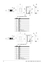
Page 13: ... 8cm 6 29 8cm 7 19 7cm 8 31 5cm 9 8 8cm 10 76cm 11 13 2cm 12 Exhaustfumesd 8cm 13 Holecombustionairinletd 6cm Fig 15 Generaldimensions Roxy LEGEND Fig 15 1 72 7cm 2 94 5cm 3 27 4cm 4 13 5cm 5 17 1cm 6 29 8cm 7 19 7cm 8 76cm 9 17 3cm 10 76cm 11 13 2cm 12 Exhaustfumesd 8cm 13 Holecombustionairinletd 6cm ...

Page 14: ... 27 5cm 4 12 5cm 5 6cm 6 30cm 7 17 5cm 8 31 5cm 9 6 5cm 10 76cm 11 13 2cm 12 Exhaustfumesd 8cm 13 Holecombustionairinletd 6cm Fig 17 Generaldimensions Tabla LEGEND Fig 17 1 71cm 2 95 5cm 3 27 5cm 4 12 5cm 5 14 5cm 6 30cm 7 18 7cm 8 76cm 9 16 5cm 10 76cm 11 13 2cm 12 Exhaustfumesd 8cm 13 Holecombustionairinletd 6cm ...

Page 15: ...Minimumlateraldistance 300mm 3 Minimumreardistance 40mm 4 Minimumfrontdistance 1000mm Itisobligatorytoinstallthestoveawayfromwallsand orpiecesoffurniture withaminimumairflowof300mmonthesides and 40 mm on the back to enable an efficient appliance cooling and a good distribution of heat in the room see Fig 19 If the walls are made up of flammable materials check the safety distances see Fig 19 At ma...

Page 16: ... bracket see Fig 21 Keep the door in a safe place until next use Fig 20 Removescrews Fig 21 Doorremoval DOOR ASSEMBLY To assemble the door you must centre the pivots fixed to the door on the structure bracket After having mounted the door with the screwdriver lift the lever so that the door is locked 5 5 GRACE3 FRAME ASSEMBLING METAL Remove the door see the dedicated chapter Place the coloured pan...

Page 17: ...s see Fig 29 supporting the stone Fig 28 Lowerbracketfixing Fig 29 Upperbracketfixing Tighten the screws to the stone see Fig 30 the screw head must protrude about 1 5 mm see Fig 31 Fig 30 Tightenthescrews Fig 31 Thescrewmustprotrude Take the stone and fit the screw head in the appropriate hole in the brackets see Fig 32 and Fig 33 Proceed in the same way for all the stones see Fig 34 Follow the p...

Page 18: ...glass Fig 35 Lowerbracketfixing Fig 36 Upperbracketfixing Tighten the screws to the glass see Fig 37 the screw head must protrude about 1 5 mm see Fig 38 Fig 37 Tightenthescrews Fig 38 Thescrewmustprotrude Take the glasses and fit the screw head in the appropriate hole in the brackets see Fig 39 and Fig 40 Proceed in the same way for all the glasses see Fig 41 Follow the procedure in reverse order...

Page 19: ... dedicated chapter Loosen the 2 screws that fix the frame to the structure see Fig 42 Release the frame see Fig 43 To assemble proceed in reverse order Fig 42 Removethescrews Fig 43 Unhookframe 5 7 ROXY ATRIUM PANEL DISASSEMBLY Remove the door see the dedicated chapter Remove the 2 screws of the faceplates located under and above the door see Fig 44 and Fig 45 and then take them out see Fig 46 ...

Page 20: ...el see Fig 49 To assemble proceed in reverse order Fig 47 Screwremoval3 Fig 48 Screwremoval4 Fig 49 Panelremoval 5 8 UPPER EXHAUST GRACE3 Proceed as follows to install the Grace3 with the upper smoke exhaust With the help of clamps break the grid near the exhaust see Fig 50 There are precuts under the grid that facilitate its removal Once the passage is open insert the d 80 mm pipe of the smoke ex...

Page 21: ...l screws and relative bolts see Fig 53 lock the pedestal to the base see Fig 54 Fig 52 Positionthestand Fig 53 Hexagonalscrewandbolt Fig 54 Lockscrews Stand the stove up and with 2 screws lock the pedestal to the back see Fig 55 Fig 55 Securethescrews 5 10 GRACE3 WALL MOUNTING OPTIONAL The stove is suitable for wall mounting The can be attached to a load bearing wall in masonry NOT plasterboard wo...

Page 22: ...le and the combustion air inlet hole EXAMPLE OF INSTALLATION OFTHE STOVE AT 8 CM FROMTHE GROUND Drill the holes in the wall for fumes extraction ref 1 and the combustion air ref 2 as indicated in Fig 57 Fix the support to the wall ref 3 using metal dowels ref 4 suitable for bearing the stove weight Secure the clamping bracket ref 5 on the back of the stove Use the screws already present on the bac...

Page 23: ...eration must be executed by an authorized technician Connect the wires from the external thermostat to the Term opt terminal on the stove board Activate the external thermostat default setting OFF as indicated below Press the menu key for a few seconds 1 Repeatedly press the P2 key until M8 Technical settings M8 SEttEcHnic appears Select by pressing the P3 key Set the password with keys P1 or P2 k...

Page 24: ...igitalpressureswitch DATA P1 P2 P3 P4 P5 Stove depression temperature 4 9 kW 20 Pa 160 C 22 Pa 170 C 24 Pa 190 C 29 Pa 195 C 33 Pa 210 C Stove depression temperature 7 kW 20 Pa 160 C 26 Pa 185 C 31 Pa 200 C 40 Pa 230 C 48 Pa 250 C NB for good combustion the depression values must be between 5 Pa and the temperature values between 10 C 6 SPECIAL MAINTENANCE 6 1 INTRODUCTION For a long working life ...

Page 25: ... Remove the inspection lid of theT union see Fig 63 Extract the ash which has accumulated in the inner After cleaning repeat the operation in reverse order checking the condition and efficiency of the gasket and if necessary replace it Itisimportanttosealedthecapothrwisenoxiuousfumeswillpropagateamongtheroom 6 3 FUME PASSAGES CLEANING Clean the fume passages every year Fig 64 Removetheinspectionca...

Page 26: ...ide for the replacement with original spare parts 6 4 HOW TO CLEAN THE ROOM FAN Clean every the year the room fan from ash or dust which can cause a blade unbalance and a greater noise MODELS SPIRIT3 ATRIUM MADISON SOLO 5 Remove the door and the front coating see dedicated chapters Vacuum the ash and dust accumulated in the fan see Fig 69 Fig 69 Roomfancleaning MODELS GRACE3 ROXY TABLA Remove the ...

Page 27: ...of the appliance This operation must be executed at least once a year 6 6 GASKET REPLACEMENT Incaseofdeteriorationoffiredoor hopperorfumechambergaskets itisnecessary toreplacethembyanautorizedtechnicianin order to guarantee the good running of the stove Useexclusivelyoriginalspareparts 7 IN CASE OF ANOMALY 7 1 PROBLEM SOLVING Before of every Authorized Technician intervention the same Technician h...

Page 28: ...l display Faulty flat cable Replace the flat cable Faulty electronic board Replace the mother board Pellets do not reach the combu stion chamber Empty hopper Full the hopper Open fire door or open pellet door Close fire door and pellet door and check that there are no pellet grains at the gasket level Clogged stove Fume chamber cleaning Auger blocked by a foreign object for example nails Clean the...

Page 29: ...otally obsturcted Contact an expert stove repairer who checks the stove from the exhaust up to the chimney pot Provide immediately for stove cleaning Obstructed stove Provide immediately at the inner cleaning of the stove The fume fan is out of order The pellets can burn also thanks to chimney flue depression without the aid of the fume fan Have the fume fan imme diately replaced It can be noxious...

Page 30: ...fume outlet limit tempe rature The stove runs at minimum NO PROBLEM The stove s smoke duct produces condensation Low smoke tempe rature Check that the flue is not clogged Increase stove power to minimum pellet drop and fan revs Install condensation collection cup Stove running and display showing SERVICE Routine main tenance alert it does not block the system When this flashing message appears upo...

Page 31: ...ve Proceed as follows Remove the frame see the dedicated chapters After these operations you can have access at the following components geared motor ignition plug ambient fan fume fan ambient probe fume probe thermostat electronic board pressostat For cleaning or replacemente of the auger it is necessary to unscrew the three bolt of the geared motor and to extract it un screw the two screws lying...

Page 32: ...m POWDER CONTENTS at 13 O2 Max 18 mg Nm3 18 mg Nm3 18 mg Nm3 CHIMNEY DEPRESSION Max 11 Pa 11 Pa 11 Pa ON SHARED CHIMNEY FLUE NO NO NO FUME OUTLET DIAMETER Ø80 mm Ø80 mm Ø80 mm COMBUSTIBLE Pellet Ø6 7 mm Pellet Ø6 7 mm Pellet Ø6 7 mm PELLETS HEATINGVALUE 5 kWh kg 5 kWh kg 5 kWh kg PELLETS HUMIDITY 10 10 10 HEATINGVOLUME 18 20 C Coeff 0 045 kW Min Max 60 118 m3 60 118 m3 60 118 m3 HOURLY CONSUMPTION...

Page 33: ...ER CONTENTS at 13 O2 Max 14 mg Nm3 14 mg Nm3 14 mg Nm3 CHIMNEY DEPRESSION Max 11 Pa 11 Pa 11 Pa ON SHARED CHIMNEY FLUE NO NO NO FUME OUTLET DIAMETER Ø80 mm Ø80 mm Ø80 mm COMBUSTIBLE Pellet Ø6 7 mm Pellet Ø6 7 mm Pellet Ø6 7 mm PELLETS HEATINGVALUE 5 kWh kg 5 kWh kg 5 kWh kg PELLETS HUMIDITY 10 10 10 HEATINGVOLUME 18 20 C Coeff 0 045 kW Min Max 65 168 m3 65 168 m3 65 168 m3 HOURLY CONSUMPTION Min M...

Page 34: ... Medium POWDER CONTENTS at 13 O2 Max 17 mg Nm3 17 mg Nm3 17 mg Nm3 CHIMNEY DEPRESSION Max 10 Pa 10 Pa 10 Pa ON SHARED CHIMNEY FLUE NO NO NO FUME OUTLET DIAMETER Ø80 mm Ø80 mm Ø80 mm COMBUSTIBLE Pellet Ø6 7 mm Pellet Ø6 7 mm Pellet Ø6 7 mm PELLETS HEATINGVALUE 5 kWh kg 5 kWh kg 5 kWh kg PELLETS HUMIDITY 10 10 10 HEATINGVOLUME 18 20 C Coeff 0 045 kW Min Max 60 125 m3 60 125 m3 60 125 m3 HOURLY CONSU...

Page 35: ...mg Nm3 Medium POWDER CONTENTS at 13 O2 Max 17 mg Nm3 CHIMNEY DEPRESSION Max 10 Pa ON SHARED CHIMNEY FLUE NO FUME OUTLET DIAMETER Ø80 mm COMBUSTIBLE Pellet Ø6 7 mm PELLETS HEATINGVALUE 5 kWh kg PELLETS HUMIDITY 10 HEATINGVOLUME 18 20 C Coeff 0 045 kW Min Max 60 125 m3 HOURLY CONSUMPTION Min Max 0 62 1 24 kg h HOPPER CAPACITY 12 kg RANGE Min Max 19 4 9 7 h SUPPLY 230V 50 Hz POWER INPUT Max 345W INGN...

Page 36: ...CADEL srl 31025 S Lucia di Piave TV Via Foresto sud 7 Italy Tel 39 0438 738669 Fax 39 0438 73343 www cadelsrl com www free point it www pegasoheating com Rev 02 2020 ...

Reviews: