Chapter 4: CSMIM-T1 Parameters
4-10
CSMIM-T1 Hardware Installation Guide
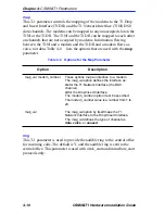
map
This T-1 parameter controls the mapping of the modems to the T1 Drop
and Insert Interface (T1DII) and the T1 Network Interface (T1NI) DS0
slots/channels. The modems can be mapped to any unoccupied slot on the
T1NI or the T1DII. The T1NI and the T1DII can be mapped to each other
on channels that are not occupied by modems. Information flowing
between the T1NI and a modem and the T1DII and a modem flows as
voice, not data. Table 4-6
lists the options that are used with the map
parameter.
Table 4-6
Options for the Map Parameter
ring
This T-1 parameter is used to provide the audible ring to the central office
for incoming calls. The default is Y, and the audible ring is sent to the
central office. This parameter is used with wink_start and immediate_start
protocols only.
Option
Description
map_val modem_number
map_val
These options map an interface to a modem.
The
map_val option defines the interface as:
ds for the T1 Network Interface (the DS0
channel).
di for the Drop/Insert Interface.
The
modem_number option must be specified.
The
modem_number value is a number from 1 to
24.
The
map_val option by itself maps the T1
Network Interface to the Drop/Insert Interface.
The
map_val defines the type of channel as
data, voice, or unused.
Summary of Contents for CSMIM-T1
Page 2: ......
Page 8: ...viii CSMIM T1 Hardware Installation Guide ...
Page 26: ...Chapter 1 INTRODUCTION 1 14 CSMIM T1 Hardware Installation Guide ...
Page 84: ...Chapter 4 CSMIM T1 Parameters 4 16 CSMIM T1 Hardware Installation Guide ...
Page 184: ...Chapter 7 AT Commands and Registers 7 58 CSMIM T1 Hardware Installation Guide ...
Page 188: ...Appendix A PORT PIN SIGNAL ALLOCATIONS A 4 CSMIM T1 Hardware Installation Guide ...


