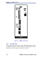
CSMIM-T1 Front Panel
CSMIM-T1 Hardware Installation Guide
1-9
RED - Red Alarm
This red indicator is ON during a locally detected carrier failure. During
the “red” alarm condition, a “yellow” alarm is transmitted to the
telephone network.
YEL - Yellow Alarm
This yellow indicator is ON when receiving a “yellow” alarm condition
from the telephone network.
BLU - Blue Alarm
This blue indicator is ON when receiving an unframed, all ones Alarm
Indication Signal (AIS) from the network. This condition exists upon a
loss of originating signal, or when any action is taken that would cause
signal disruption.
1.6.6
Modem Configuration Status LEDs
To help determine if a problem exists in a modem, there are three
green/amber LEDs labeled 1-8, 9-16, and 17-24. These LEDs indicate
groups of modems installed. When amber, the LED indicates that at least
one modem within the indicated group is in a fault condition. When
green, the LED indicates that diagnostics have determined that the
modems are operating normally.
1.6.7
Modem Port Status LEDs
Each modem has a group of three LEDs to indicate activity. These LEDs
can help determine a fault within a group of modems.
CD - Carrier Detect
This green LED is ON when the carrier has been detected on the
telephone line of the corresponding modem. There are a total of 24 CD
indicators, one per channel.
TX - Transmit Data
This green LED flashes to indicate the corresponding modem is
transmitting data. There are a total of 24 TX indicators, one per channel.
RX - Receive Data
This green LED flashes to indicate the corresponding modem is receiving
data. There are a total of 24 RX indicators, one per channel.
Summary of Contents for CSMIM-T1
Page 2: ......
Page 8: ...viii CSMIM T1 Hardware Installation Guide ...
Page 26: ...Chapter 1 INTRODUCTION 1 14 CSMIM T1 Hardware Installation Guide ...
Page 84: ...Chapter 4 CSMIM T1 Parameters 4 16 CSMIM T1 Hardware Installation Guide ...
Page 184: ...Chapter 7 AT Commands and Registers 7 58 CSMIM T1 Hardware Installation Guide ...
Page 188: ...Appendix A PORT PIN SIGNAL ALLOCATIONS A 4 CSMIM T1 Hardware Installation Guide ...


