9033381
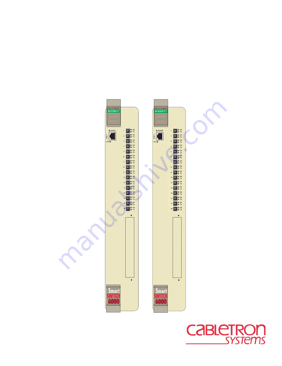
6H258-17 and 6H259-17
SmartSwitch 6000 Interface Modules
Installation User’s Guide
Page 1: ...9033381 6H258 17 and 6H259 17 SmartSwitch 6000 Interface Modules Installation User s Guide...
Page 2: ......
Page 3: ...LOST PROFITS ARISING OUT OF OR RELATED TO THIS MANUAL OR THE INFORMATION CONTAINED IN IT EVEN IF CABLETRON SYSTEMS HAS BEEN ADVISED OF KNOWN OR SHOULD HAVE KNOWN THE POSSIBILITY OF SUCH DAMAGES Cable...
Page 4: ...case the user will be required to correct the interference at his own expense WARNING Changes or modifications made to this device which are not expressly approved by the party responsible for complia...
Page 5: ...of the Program provided in this package subject to the terms and conditions of this License Agreement You may not copy reproduce or transmit any part of the Program except as permitted by the Copyrigh...
Page 6: ...submitted with restricted rights in accordance with section 52 227 19 a through d of the Commercial Computer Software Restricted Rights Clause and its successors and iii in all respects is proprietar...
Page 7: ...to regulation by agencies of the U S Government including the U S Department of Commerce which prohibit export or diversion of certain technical products to certain countries unless a license to expo...
Page 8: ...cumentation and media CABLETRON DISCLAIMS ALL WARRANTIES OTHER THAN THOSE SUPPLIED TO YOU BY CABLETRON IN WRITING EITHER EXPRESS OR IMPLIED INCLUDING BUT NOT LIMITED TO IMPLIED WARRANTIES OF MERCHANTA...
Page 9: ...he right to use only the one 1 copy of the Program provided in this package subject to the terms and conditions of this License Agreement You may not copy reproduce or transmit any part of the Program...
Page 10: ...e submitted with restricted rights in accordance with section 52 227 19 a through d of the Commercial Computer Software Restricted Rights Clause and its successors and iii in all respects is proprieta...
Page 11: ...andardization When operating within their performance limitations laser transceiver output meets the Class 1 accessible emission limit of all three standards Class 1 levels of laser radiation are not...
Page 12: ...60950 Equipment Type Environment Networking Equipment for use in a Commercial or Light Industrial Environment We the undersigned hereby declare under our sole responsibility that the equipment packag...
Page 13: ...4 SmartTrunk 1 4 1 1 5 Remote Monitoring RMON 1 4 1 1 6 Broadcast Suppression 1 4 1 1 7 Port VLAN Redirect Functions 1 4 1 1 8 Rate Limiting 1 5 1 1 9 GARP Switch Operation 1 5 1 1 10 Flow Control 1...
Page 14: ...tallation 3 6 4 TROUBLESHOOTING 4 1 Using LANVIEW 4 1 4 2 Troubleshooting Checklist 4 5 4 3 Using the RESET Button 4 10 A SPECIFICATIONS A 1 Module Specifications A 1 A 2 Physical Properties A 1 A 3 E...
Page 15: ...rface Module 3 3 3 2 Connecting a Fiber Optic Segment to the SmartSwitch 3 5 4 1 LANVIEW LEDs 4 2 4 2 RESET Button 4 10 B 1 Module Mode Switch Location Component Layout B 2 B 2 SIMM Slot Locations B 4...
Page 16: ...ipping Container 3 1 4 1 LANVIEW LEDs 4 3 4 2 Fault Identification 4 5 4 3 Power System Troubleshooting 4 6 4 4 Firmware Troubleshooting 4 7 4 5 Management System Troubleshooting 4 8 4 6 Device Setup...
Page 17: ...l working knowledge of Fast Ethernet and IEEE 802 3 type data communications networks and their physical layer components is helpful when using these devices Important Notice Depending on the firmware...
Page 18: ...k requirements that must be met before installing the SmartSwitch into the 6C105 SmartSwitch 6000 chassis Chapter 3 Installation provides instructions on how to install the module in the chassis and c...
Page 19: ...F6 User s Guide HSIM FE6 User s Guide HSIM W6 User s Guide HSIM W84 User s Guide HSIM W87 User s Guide HSIM G01 G09 User s Guide VHSIM G6 User s Guide VHSIM A6DP User s Guide WAN Series Local Managem...
Page 20: ...on to any item of information that may be of special importance TIP Tip symbol Conveys helpful hints concerning procedures or actions CAUTION Caution symbol Contains information essential to avoid dam...
Page 21: ...tional HSIMs provide one or more high speed uplinks to other networking technologies such as Gigabit Ethernet Fast Ethernet Fiber Distributed Data Interface FDDI Wide Area Network WAN and Asynchronous...
Page 22: ...Overview 1 2 Introduction Figure 1 1 The SmartSwitch Port Status LEDs CPU LED COM Port Network Ports 1 16 Reset VHSIM HSIM Slot...
Page 23: ...is connected to the network and powered up Runtime IP Address Discovery RAD checks the module for an IP address If one has not yet been assigned module and 6C105 chassis IP address set to 0 0 0 0 RAD...
Page 24: ...s RMON Actions is a vendor specific extension of RMON and provides the ability to set an Action on any SNMP MIB variable The Action can be triggered by setting an RMON Event and or Alarm An example of...
Page 25: ...it frames are dropped until the rate falls below the limit Administrators can configure up to four rate limit rules per port however each rule must not include conflicting 802 1p priority values In or...
Page 26: ...can be enabled or disabled on a port by port basis 1 1 11 802 1 Port Priority IEEE 802 1 port priority is incorporated in the IEEE 802 1D standard It is used to assign a default priority to the frame...
Page 27: ...ngs are done by selecting the specific module to be modified and changing the settings for that module 1 1 15 Optional HSIMs and VHSIMs The SmartSwitches provide a slot for an optional High Speed Inte...
Page 28: ...n of any action s already taken to resolve the problem e g changing mode switches rebooting the unit etc The serial and revision numbers of all involved Cabletron Systems products in the network A des...
Page 29: ...that the network meets the optical performance requirements for 100BASE FX IEEE 802 3u standard One module the 6H258 17 is made specifically for multimode fiber optic cable and the other the 6H259 17...
Page 30: ...hs of up to 15 km 2 2 SmartTrunk To connect the SmartSwitch modules to a network to take advantage of the SmartTrunk feature there are certain rules concerning port connections and configurations that...
Page 31: ...tion 3 5 3 1 UNPACKING THE SMARTSWITCH 1 Open the box and remove the packing material protecting the module 2 Verify the contents of the carton as listed in Table 3 1 Only qualified personnel should i...
Page 32: ...d to ensure proper airflow and cooling Save the blank plate in the event you need to remove the module 2 Carefully remove the module from the shipping box Save the box and packing materials in the eve...
Page 33: ...he module Immediately contact Cabletron Systems Refer to Section 1 2 1 2 3 4 5 PS1 PS2 Plastic Locking Tab Slot Number 2159 01 Circuit Card Card Guides Metal Back Panel Plastic Locking Tab Backplane C...
Page 34: ...section provides the procedures for connecting segments from the network or other devices to the SmartSwitch CAUTION To prevent damaging the backplane connectors in the following step take care that t...
Page 35: ...release tab catches as shown in Figure 3 2 NOTE Leave protective covers on the fiber optic cable or fiber optic ports until they are connected to protect the connectors from dust and dirt If a segmen...
Page 36: ...ons outlined in the Cabletron Systems Cabling Guide Refer to the Related Manuals in the About This Guide preface for information on obtaining this document 4 If a link is not established refer to Chap...
Page 37: ...c and status monitoring system called LANVIEW The LANVIEW LEDs Figure 4 1 allow quick observation of the network status to aid in diagnosing network problems Refer to Table 4 1 for a description of th...
Page 38: ...Using LANVIEW 4 2 Troubleshooting Figure 4 1 LANVIEW LEDs Receive LED Transmit LED CPU LED...
Page 39: ...s Amber Blinking Crippled Contact Cabletron Systems Solid Testing If the LED remains amber for several minutes contact Cabletron Systems Green Solid Functional None Amber and Green Booting Blinks ambe...
Page 40: ...ty Rate indicates data rate None Amber Blinking Port in standby Port may be disabled due to Spanning Tree 1 Ensure that the port is not disabled Refer to your Local Management User s Guide for informa...
Page 41: ...otP server on the network Press the RESET button on the front panel to attempt to use the firmware image in FLASH memory 2 If the problem continues after pressing the RESET button refer to Section B 1...
Page 42: ...the chassis 2 If the SmartSwitch functions in the selected slot the SmartSwitch onboard power converter is operational The 6C105 chassis power bus may have a localized fault Install the SmartSwitch in...
Page 43: ...nsole port pinouts The COM port of the device has been disabled or the COM port application has been changed 1 Establish a Telnet connection to the device 2 Refer to your Local Management User s Guide...
Page 44: ...ave an IP address 1 Refer to your Local Management User s Guide for IP address assignment procedure 2 If the SmartSwitch are using the IP address of the 6C105 chassis ensure that the modules are not i...
Page 45: ...red parameters to reset to factory default settings 1 Reenter the lost parameters as necessary Refer to the Local Management User s Guide for instructions on configuring the device through Local Manag...
Page 46: ...cessor goes through a reset process of approximately 60 seconds Additional downtime may be added as the module reenters the network CAUTION Pressing the RESET button resets the device and all current...
Page 47: ...s the right to change these specifications at any time without notice A 1 MODULE SPECIFICATIONS A 2 PHYSICAL PROPERTIES Processor Intel i960 RISC processor control Power PC Dynamic Random Access Memor...
Page 48: ...nsing Ports 1 through 16 Fast Ethernet 100 Mbps 100BASE FX compliant with MT RJ connectors 6H258 17 using multimode fiber only 6H259 17 using single mode fiber only Slot for optional High Speed Interf...
Page 49: ...ps 100BASE FX compliant with MT RJ connectors using single mode fiber Options for both the 6H258 17 and the 6H259 17 Slot for optional High Speed Interface Module HSIM or Very High Speed Interface Mod...
Page 50: ......
Page 51: ...otP server Clear NVRAM and restore all user entered parameters such as the IP address and Subnet Masks to the SmartSwitch Default configuration settings Clear user entered passwords stored in NVRAM an...
Page 52: ...l Management sessions Changing the switch to the ON position disables Autobaud sensing and sets the COM port to 9600 baud for Local Management sessions Switch 6 Forced BootP Changing the position of t...
Page 53: ...ed to their factory default settings Switch 8 Reset Password Community Strings Changing the position of this switch clears only the user entered passwords stored in NVRAM and restores the default pass...
Page 54: ...roceed as follows 1 With the SIMM alignment notch oriented as shown in Figure B 3 insert the SIMM down between the connector teeth 2 Pivot the SIMM downward so the connector clips align with the two s...
Page 55: ...MODULES Figure B 4 shows the location of the two connectors for an optional High HSIM or VHSIM Depending on if an HSIM or VHSIM is installed one or both connectors are used NOTE Refer to the installa...
Page 56: ...Installing Optional High Speed Interface Modules B 6 Switch Settings Upgrades and Installations Figure B 4 HSIM and VHSIM Connector Locations Optional HSIM or VHSIM DRAM HSIM VHSIM Connectors...
Page 57: ...stallation connecting to the Network 3 4 High Speed Interface Module B 5 Module 3 1 Very High Speed Interface Module B 5 L LANVIEW LEDs 4 1 LDRAM installation B 5 Local Management introduction 1 6 M M...
Page 58: ...er ix SDRAM installation B 5 SIMMs installing LDRAM B 4 location B 3 SmartTrunk introduction to 1 4 Specifications A 1 Standards compatibility 1 7 T Troubleshooting 4 1 checklist 4 5 U Unpacking 3 1 V...