background image

8

8

2 Installation

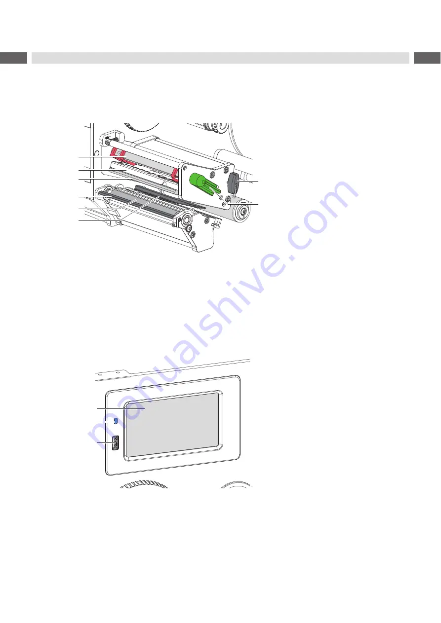
20

13
14

15

16

19

17
18

13  Head locking system
14  Printhead retainer
15  Printhead
16  Peel-off edge
17  Print roller
18  Label sensor
19  Allen key
20  Printhead locking lever

Figure 4 

Print mechanism

21
22

23

21  Touchscreen display
22  LED Power ON
23  USB host interface  

for USB memory stick or service key

Figure 5 

Control panel

Summary of Contents for HERMES Q2L

Page 1: ...Assembly Instructions HERMES Q MADE IN GERMANY Label Printer...

Page 2: ...rding questions or suggestions please contact cab Produkttechnik GmbH Co KG Germany Topicality Due to the constant further development of our products discrepancies between documentation and product m...

Page 3: ...Guiding the Liner to the Internal Rewinder 17 4 2 Setting the Head Locking System 18 4 3 Setting the Peel off Edge 18 4 4 Loading Transfer Ribbon 19 4 5 Setting the Feed Path of the Transfer Ribbon 2...

Page 4: ...splay monitor 1 2 Intended Use The printer is designed for the integration into a production line It is intended exclusively for printing suitable materials that have been approved by the manufacturer...

Page 5: ...r at the outside only Do not reach into the swivel range of the cover Perform only those actions described in this operating manual Work going beyond this may only be performed by trained personnel or...

Page 6: ...into contact with the exposed rotating parts 1 5 Environment Obsolete devices contain valuable recyclable materials that should be sent for recycling X X Send to suitable collection points separately...

Page 7: ...l retainer 9 Pivot arm with guide roller 10 Internal rewinder 11 Guide roller 12 Transport system Figure 2 Overview HERMES Q 2 3 2 2 4 5 6 7 8 9 10 11 12 2 Hinges for cab applicators 3 Control panel 4...

Page 8: ...nthead retainer 15 Printhead 16 Peel off edge 17 Print roller 18 Label sensor 19 Allen key 20 Printhead locking lever Figure 4 Print mechanism 21 22 23 21 Touchscreen display 22 LED Power ON 23 USB ho...

Page 9: ...onnection jack 26 Slot for SD card 27 2 USB host interfaces for service key USB memory stick keyboard barcode scanner Bluetooth adapter WiFi adapter external control panel or warning light 28 USB Hi s...

Page 10: ...eep the original packaging in case the printer must be returned Attention The device and printing materials will be damaged by moisture and wetness X X Set up printers only in dry locations protected...

Page 11: ...ocket 2 3 2 Connecting to a Computer or Computer Network Attention Inadequate or no grounding can cause malfunctions during operations Ensure that all computers and cables connected to the printer are...

Page 12: ...nds Programming Manual for details Settings made on the touchscreen display make the basic settings of the label printer i Note It is advantageous whenever possible to make adaptations to various prin...

Page 13: ...on manual All received data are stored in a lbl file Warning ribbon end Configuration manual The remaining diameter of the ribbon supply roll undershoots the set value SD card installed USB memory ins...

Page 14: ...level is reached X X Start a function The will carry out the function possibly after a preparing dialogue or Select a parameter to set The setup possibilities are depending from the parameter type Log...

Page 15: ...ading label roll 1 Turn knob 5 clockwise to release the roll retainer 4 2 Remove the margin stop 6 from the roll retainer 3 Load label roll 2 on the roll retainer 4 in such a way that the labels are v...

Page 16: ...the label strip over the peel off edge 1 that the strip reaches back internal rewinder Remove the labels from the overhanging strip 4 1 3 Setting the Label Sensor 1 3 2 4 Figure 14 Setting the Label S...

Page 17: ...the knob 4 clockwise until it stops 3 Guide the liner coming from the peel off edge around the transport roller 5 and the locking system 6 to the internal rewinder 1 4 Push the liner under a bracket...

Page 18: ...unger 2 with the Allen key 3 Align the outer plunger 2 to the outer label edge and tighten the threaded pin 1 4 3 Setting the Peel off Edge When operating the printer with applicator the label must be...

Page 19: ...es away from the printhead after loading 4 Hold ribbon supply hub 4 firmly and turn knob 5 counterclockwise until the transfer ribbon roll is secured 5 Slide suitable ribbon core 1 onto the transfer r...

Page 20: ...ing X X Check first the setting of the head locking system 4 2 on page 18 2 1 3 Figure 20 Setting the feed path of the transfer ribbon i Note The adjustment is best carried out during printing 1 Read...

Page 21: ...not be lost by switching off the printer as long as the printhead and the transport system are kept close 5 3 Peel off Mode In Peel off mode the labels are automatically peeled off the liner after pr...

Page 22: ...impair the media transport and the print quality X X Lift the printhead X X Remove labels and transfer ribbon from the printer X X Remove deposits with roller cleaner and a soft cloth X X If the rolle...

Page 23: ...e size of the barcode or move it Buffer overflow The input buffer memory is full and the computer is still transmitting data Use data transmission via protocol preferably RTS CTS Device not conn Progr...

Page 24: ...emory card Check data of the card Backup data reformat card Remove ribbon Transfer ribbon is loaded although the printer is set to direct thermal printing for direct thermal printing remove ribbon for...

Page 25: ...CII dump mode Cancel the ASCII dump mode Printer transports label media but transfer ribbon does not move Transfer ribbon incorrectly inserted Check and if necessary correct the transfer ribbon web an...

Page 26: ...ight 3 200 4 320 6 320 A Label distance 2 C Width of liner 24 62 24 118 46 178 Dl Left margin 0 Dr Right margin 0 E Label thickness 0 03 0 60 F Liner thickness 0 03 0 16 G Thickness label with liner 0...

Page 27: ...0 dpi 1 0 1 0 1 0 1 0 1 0 1 0 1 0 1 0 1 0 1 0 1 0 1 0 1 0 1 0 1 0 1 0 with ribbon saver 203 dpi 300 dpi 600 dpi 1 0 1 0 1 0 1 0 2 2 0 0 1 6 0 7 0 2 2 9 0 2 2 9 K Print width 203 dpi 300 dpi 600 dpi 56...

Page 28: ...e mark material edge 2 26 2 60 Z Distance virtual label front edge actual label front edge X X Adjust software settings 0 up to A recomm 0 Reflex marks must be on the back side of the material liner L...

Page 29: ...f cut out mark 2 10 X Distance mark material edge 2 26 2 60 Y Sensor recognized virtual label front edge with gap sensor recognition Rear edge cut out Z Distance recognized front edge actual label fro...

Page 30: ...30 30 9 Assembly Dimensions Figure 27 Assembly dimensions HERMES Q 2 Figure 28 Assembly dimensions HERMES Q 3...

Page 31: ...ISO 12100 2010 EN ISO 13857 2008 EN 349 1993 A1 2008 EN ISO 13849 1 2015 EN 62368 1 2014 AC 2015 Other Relevant Directives Directive 2014 30 EU relating to electromagnetic compatibility Directive 201...

Page 32: ...N 50581 2012 Commission delegated directive EU 2015 863 amending Annex II to Directive 2011 65 EU of the European Parliament and of the Council as regards the list of restricted substances Signed for...

Page 33: ...ead locking system setting 18 I Important information 4 Intended use 4 L Label sensor setting 16 License 2 Lithium battery 6 Loading labels 15 Loading transfer ribbon 19 P Peel off mode 21 Power suppl...

Reviews: