31
6
Troubleshooting and Error Treatment
6.1
Failure of Device Functions
Functional error
Possible remedy
Medium is not transported
Check electrical connections between PCB CPU and motor
Check drive mechanism
Replace the PCB Electronics
Replace the PCB CPU
Replace the motor
No print image with medium
transport
Check the ribbon saver setting
Check plug connections at the printhead
Examine printhead cable for damage and replace if necessary
Replace the printhead
Replace the PCB Electronics
Replace the PCB CPU
No display and navigator pad
function
Check whether LED1 (green) is illuminating on the PCB CPU
•
LED1 is not illuminating: The power supply unit or CPU PCB is defective.
Replace PCB CPU or Power supply unit.
•
LED1 flashes: Firmware update unsuccessful.
Reload the firmware
Configuration Manual
Check cable connection between PCB CPU and control panel
Check whether the correct voltages are active at the 3,3 V and 5 V measurement
points on the PCB CPU
•
No voltage at either measurement point: The power supply unit may be
defective. Replace the power supply unit
•
No voltage at one measurement point: The PCB CPU may be defective.
Replace the PCB CPU.
Replace LCD Display
Replace PCB Navi Button
No display function, but the
navigator pad is functioning
Replace LCD Display
No navigator pad function, but
the display is functioning
Check the cable connection between LCD Display cpl. and PCB Navi Button and
replace if necessary
Replace PCB Navi Button
Replace LCD Display
Communication via an interface
is not functioning
Check whether the interface configurations of the printer and computer match
For an Ethernet connection, check the validity of the IP address and the subnet
mask
Check the interface cable and replace it if necessary
If all functionality of the interface has been lost, replace the PCB CPU
Communication via the
interface on the PCB I/O
Interface is not functioning
Check the cable and it's necessary change it.
Replace PCB I/O Interface.
Check connection between PCB USB Hub and PCB CPU .
Replace PCB USB Hub.
Table 3
Failure of device functions
Summary of Contents for Hermes C 6L
Page 1: ...Made in Germany Service Manual Hermes C Label Printer ...
Page 33: ...33 7 Block Diagram Figure 34 Block diagram Hermes C ...
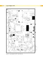
Page 34: ...34 34 8 Layout Diagram CPU Figure 35 Layout diagram PCB CPU components side ...
Page 35: ...35 Figure 36 Layout diagram PCB CPU soldering side 8 Layout Diagram CPU ...


