background image

20

20

Loading Material

4.5 

Loading Transfer Ribbon

i

Notice! 

With direct thermal printing, do not load a transfer ribbon; if one has already been loaded, remove it.


1

3

4

5

2

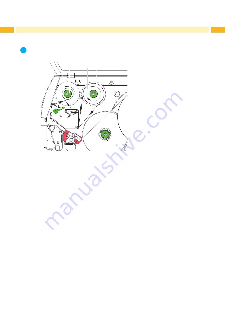
Fig. 14 

Feed path of the transfer ribbon

1.  Clean printhead before loading the transfer ribbon (

 6.3 on page 25).

2.  Turn lever (5) counterclockwise to lift the printhead.
3.  Slide transfer ribbon roll (3) onto the ribbon supply hub (4) until it stops and so that the color coating of the ribbon 

faces downward when being unwound. No rotation direction is specified for the ribbon supply hub (4).

4.  Hold transfer ribbon roll (3) firmly and turn knob on ribbon supply hub (4) counterclockwise until the transfer ribbon 

roll is secured. 

5.  Slide suitable transfer ribbon core (1) onto the transfer ribbon take-up hub (2) and secure it in the same way.
6.  Guide transfer ribbon through the print unit as shown in Fig. 17.
7.  Secure starting end of transfer ribbon to the transfer ribbon core (1) with adhesive tape. Ensure counterclockwise 

rotation direction of the transfer ribbon take-up hub here. 

8.  Turn transfer ribbon take-up hub (2) counterclockwise to smooth out the feed path of the transfer ribbon. 
9.  Turn lever (5) clockwise to lock the printhead.

Summary of Contents for A+

Page 1: ...Label Printer Operator s Manual A The Premium Class...
Page 2: ...e latest update Terms and conditions Deliveries and performances are effected under the General conditions of sale of cab Operator s Manual for the following products Germany cab Produkttechnik GmbH C...

Page 3: ...ind Mode 15 4 2 5 Winding up the Liner in Peel Off mode 16 4 2 6 Setting the Head Locking System 17 4 3 Removing the Wound Roll 18 4 4 Loading Fanfold Labels 19 4 5 Loading Transfer Ribbon 20 4 6 Sett...

Page 4: ...ly for printing suitable materials that have been approved by the manufac turer Any other use or use going beyond this shall be regarded as improper use The manufacturer supplier shall not be liable f...

Page 5: ...ckers on the device They draw your attention to dangers Warning stickers must therefore not be removed as then you and other people cannot be aware of dangers and may be injured The maximum sound pres...

Page 6: ...for accessories incl peripheral connector 9 Navigator pad 10 Display Fig 1 Overview 12 13 14 18 19 16 11 20 21 15 17 11 Ribbon deflection 12 Printhead locking screw 13 Printhead retainer with printhea...

Page 7: ...memory card 26 Ethernet 10 100 Base T 27 2 USB master ports for keyboard scanner or service key 28 USB high speed slave port 29 Serial RS 232 C port Fig 3 Connections 30 30 Support bracket A8 only fo...

Page 8: ...e 3 2 3 1 Connecting to the Power Supply The printer is equipped with a wide area power unit The device can be operated with a supply voltage of 230 V 50 Hz or 115 V 60 Hz without adjustment 1 Check t...

Page 9: ...various print jobs in the software 1 2 Ready 6 The control panel consists of a graphic display 1 and the navigator pad 2 with five integrated keys The graphic display indicates the current status of...

Page 10: ...l to be printed An error has occurred that can be rectified by the operator without interrupting the print job The print job can be continued after the error has been rectified Irrecoverable error and...

Page 11: ...te cancel lights Ready Ready Delete internal memory the last label can no longer be reprinted Printing label Printing label Short press g cancels the current print job Longer press g cancels the curre...

Page 12: ...ribed in the following chapters 1 2 3 3 3 2 3 3 1 Fig 6 Support bracket A8 Opening the Support Bracket X X Open cover X X Turn lever 2 counterclockwise to lift the printhead X X Open the support brack...

Page 13: ...gin stop 1 onto the roll retainer 4 Push the margin stop 1 to the roll until it stops 6 Turn ring 2 clockwise so that the arrow 10 points to the symbol and thus fix the margin stop 1 on the roll retai...

Page 14: ...unit and is marked with a indentation in the label sensor retainer X X Position label sensor with tab 3 in such a way that the sensor 1 can detect the label gap or a reflex or perfo ration mark or if...

Page 15: ...page 22 2 Guide label strip around the rewind guide plate 4 to the internal rewinder 2 3 Hold rewinder 2 firmly and turn knob 3 clockwise until it stops 4 Push label strip under a bracket 1 of the rew...

Page 16: ...rewind assist roller 5 4 Hold rewinder 2 firmly and turn knob 3 clockwise until it stops 5 Push liner under a bracket 1 of the rewinder 2 and turn knob 3 counterclockwise until it stops The rewinder...

Page 17: ...el width prevent wrinkles in the feed path of the transfer ribbon prevent premature wearing of the print roller and printhead 1 2 3 1 2 3 1 4 Fig 11 Setting the head locking system 1 Turn lever 3 cloc...

Page 18: ...the wound roll 1 Turn lever 1 counterclockwise to lift the printhead 2 Cut label strip and wind it fully around the rewinder 3 3 Hold rewinder 3 firmly and turn knob 2 clockwise The rewinder spindle r...

Page 19: ...le from above 4 Guide label strip to print unit via the roll retainer 3 5 Move the margin stop 1 against the media strip until chassis 5 and margin stop 1 touch the media strip without clamping or ben...

Page 20: ...otation direction is specified for the ribbon supply hub 4 4 Hold transfer ribbon roll 3 firmly and turn knob on ribbon supply hub 4 counterclockwise until the transfer ribbon roll is secured 5 Slide...

Page 21: ...ay also cause ribbon wrinkling 4 2 6 on page 17 1 2 Fig 15 Setting the feed path of the transfer ribbon i Notice The adjustment is best carried out during printing 1 Read current setting on the scale...

Page 22: ...ersions with a locking system on the rewind assist roller the locking system must be removed for operation in rewind mode before installation of the rewind guide plate 4 8 on page 23 2 2 1 Fig 16 Remo...

Page 23: ...screws 1 2 and remove them 3 Remove the pinch roller 4 and bottom plate 3 Installing the locking system 1 Position printer at edge of table so that the oblong hole is accessible from below 2 Place th...

Page 24: ...or cut during the synchronization i Notice Synchronization is not necessary if the printhead was not opened between different print jobs even if the printer was switched off 5 2 Tear off Mode In tear...

Page 25: ...may impair the media transport and the print quality X X Lift the printhead X X Remove labels and transfer ribbon from the printer X X Remove deposits with roller cleaner and a soft cloth X X If the r...

Page 26: ...The label sensor can become dirtied with paper dust This can adversely affect label detection 1 2 3 4 Fig 18 Cleaning the label sensor 1 Turn lever 1 counterclockwise to lift the printhead 2 Remove l...

Page 27: ...nting is chosen in the software Change to thermal transfer printing Printer prints a sequence of characters instead of the label format Printer is in ASCII dump mode Cancel the ASCII dump mode Printer...

Page 28: ...f and then on If error recurs call service Head error Hardware error Switch the printer off and then on If error recurs replace printhead Head open Printhead not locked Lock printhead Head too hot Pri...

Page 29: ...the computer Press the pause key to skip the command or press the cancel key to cancel the print job Read error Read error when reading from the memory card Check data of the card Backup data reforma...

Page 30: ...cutter with perforation cutter 2 12 Perforation length 2 A Label distance 2 C Width of liner or endless material 25 67 25 120 50 180 50 235 Dl Left margin 0 Dr Right margin 0 E Label thickness 0 025 0...

Page 31: ...ge 203 dpi 300 dpi 600 dpi 2 0 2 0 2 0 2 0 2 0 2 0 2 0 0 4 3 1 2 0 K Print width 203 dpi 300 dpi 600 dpi 54 2 57 0 104 0 105 6 105 6 104 0 108 4 168 0 162 6 216 0 SX Distance gap reflective sensor mat...

Page 32: ...dge for A2 for A4 A4 3 A6 A8 5 26 5 53 Z Distance virtual label front edge actual label front edge X X Adjust software settings 0 up to A recomm 0 Reflex marks must be on the back side of the material...

Page 33: ...ght of cut out mark 2 10 X Distance mark material edge for A2 for A4 A4 3 A6 A8 5 26 5 53 Y Sensor recognized virtual label front edge with gap sensor recognition Rear edge cut out Z Distance recogniz...

Page 34: ...1 A1 2010 EN 61558 1 2005 A1 2009 Directive 2004 108 EC relating to electromagnetic compatibility EN 55022 2010 EN 55024 2010 EN 61000 3 2 2006 A1 2009 A2 2009 EN 61000 3 3 2008 Signed for and on beha...

Page 35: ...menu 11 print mode 11 L Label dimensions 30 Label sensor adjusting 14 cleaning 26 Lithium battery 5 Loading fanfold labels 19 Loading labels 13 Loading labels from roll 13 Loading transfer ribbon 20 L...

Page 36: ...36 36 This page was intentionally left blank...

Reviews: