background image


BXB ELECTRONICS CO., LTD.


11 

Copyright © 2011 BXB ELECTRONICS CO., LTD. All rights reserved. 

LCD Instructions 


1. 

Using microphones ID code:   

3

 groups of ID code are displayed per page. 

Chairman MIC

*01 -*10     Delegate MIC

001 ~ 999 

2. 

Mode - Normal : Normal Mode   Override : Override Mode 

Chairman : Chairman Mode   FIFO : First in first out (FIFO) mode 

3. 

OPEN-MIC: three modes of limiting the number of simultaneously usable units: 1~30, all 

open and chairman mode. 

4. 

AUTO-OFF (Automatic Mic-off): 

10 ~ 99

 second & and manual turn off. 

5. 

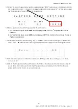
SPEED DOME SETTING: Displays and settings of Speed Dome & chairman/delegate 

microphone. ID code 


6. 

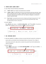
SPEED DOME MODE: 

None

Stop Auto-Image Tracing & Positioning function 

Button

When pressing the “Talk” button, the auto image tracing and positioning mode is 

activated. 

Voice

When using more than two microphones, speed dome will be automatically 

detected the voice for executing auto image tracing and positioning mode. 


1    N  O  : 


2    M  O  D  E  : 

  N  o  r  m  a  l 


3    O  P  E  N  -  M  I  C  : 

  0  2    M  i  c   


4    A  U  T  O  -  O  F  F  : 

  3  0    S  e  c   


5    S  P  E  E  D    D  O  M  E    S  E  T  T  I  N  G 


  M  I  C   


  D  O  M  E   


  A  D  R   


(  0  0  1  ) 


  0  1   


  0  0  1   


6    S  P  E  E  D    D  O  M  E    M  O  D  E   


(  N  o  n  e  ) 

  B  u  t  t  o  n    V  o  i  c  e   


Summary of Contents for UFO-2050

Page 1: ... CO LTD All rights reserved U UF FO O 2 20 05 50 0 C Co on nf fe er re en nc ce e S Sy ys st te em m U Us se er r M Ma an nu ua al l V V Ve e er r rs s si iio o on n n 1 1 1 0 0 0 D D Da a at tte e e M M Ma a ar r rc c ch h h 3 3 30 0 0 2 2 20 0 01 1 11 1 1 ...

Page 2: ...scription 9 Turn On 10 LCD Instructions 11 Operations Settings 13 1 USING MIC ID 13 2 CONFERENCE MODE 14 3 OPEN DELEGATE MICROPHONE NUMBER 16 4 MIC AUTO OFF TIME 16 Save Setting 17 5 SPEED DOME CAMERA SETTING 17 6 SPEED DOME CAMERA MODE 19 7 MIC CHECKING MODE 19 8 SPEED DOME RETURN 21 9 VIDEO AUTO SWITCH 22 Volume Mode Settings 23 MIC Volume Mode Settings 23 AUX Volume Mode Settings 23 Tabletop Ch...

Page 3: ...y meet your requirements for any occasion High speed 360 endless rotation and auto return enable BXB dome camera to be applied in various image positions RS 485 communication interface could apply to remote control 128 programmable preset points facilitate setting positions more precisely The main control unit runs auto detection to check if all the units work properly when turning on facilitating...

Page 4: ...ume 3 Built In digital volume control module 4 Built In image tracing positioning control module 5 Built In software control communication Interface Chairman Unit 1 Types Tabletop and flush mounted 2 Microphone on off button control button 3 Pliable in anywhere within circuit 4 ID Setting 10 Bits DIP Switches 5 Chairman ID code 01 10 10 units at most Delegate Unit 1 Types Tabletop flush mounted an...

Page 5: ...emperature 0 C 40 C 32 F 104 F humidity below 90 9 Please do not switch on and off the apparatus rapidly Rapid switch on and off the apparatus should be avoided all the time to prevent inside sensitive electronic circuits from being damaged by surges 10 Do not clean the apparatus and its accessories with chemical solvents Use only a clean dry dampish cloth 11 Refer to maintenance technician when t...

Page 6: ...rophone links in the back of main control unit which can be connected randomly 1 2 Microphone units are equipped with hidden sockets for connecting Cat 5e cable featuring simple and beautiful appearance 1 3 Chairman units are pliable in anywhere within circuit 1 4 Please make sure the power is off before unplugging any unit Up to 25 PCS CAT 5 Cable CAT 5 Cable Up to 25 PCS ...

Page 7: ...tion D D Maximum 16 speed dome cameras can be connected 2 4 If connecting cord is needed to be made by you please refer to the Appendix control plug instruction 2 5 The position of RS 485 connector of speed dome can the plug position please refer to the Appendix 2 6 The material of control cords could be referred to the Appendix 3 Connection between main control unit software 3 1 The main control ...

Page 8: ...ce function control MODE Mode changing UP Gain parameter setting conference volume up DN Reduce parameter setting conference volume down STEP Select parameter setting of the IP speed dome from left to right SAVE Save settings 3 Volume output LED indicator 4 20 4 bits LCD screen 8 5 0 2 2 Mode Up Down Power Conference System Control Unit 1 2 3 4 Down Down ...

Page 9: ... 1 Operating voltage DC 18V 6A host 2 DC power supply fuse DC 250V 8A 3 High speed dome camera rotation port 4 Graphical software RS 232 port 5 LINK 1 4 Microphone output 6 L Spearer VR Microphone built in speaker volume knob 7 AUX output terminal XLR AUX output terminal description 1 3 Ground 2 Sound Aux ...

Page 10: ...n control unit is ON this conference system will be executed microphone connection test At this moment the red LED of microphone will be constantly on 5 seconds later if the connection was wrong the faults unit will be flashing It means the connection is failure 2 In this case the power of main control unit should be switched off and check whether the microphone connection is correct or not and th...

Page 11: ...c off 10 99 second and manual turn off 5 SPEED DOME SETTING Displays and settings of Speed Dome chairman delegate microphone ID code 6 SPEED DOME MODE None Stop Auto Image Tracing Positioning function Button When pressing the Talk button the auto image tracing and positioning mode is activated Voice When using more than two microphones speed dome will be automatically detected the voice for execut...

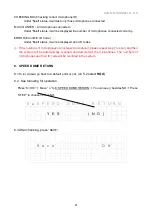
Page 12: ... scan Scanning all the units is a must do when first starts the system 8 SPEED DONE RETURN YES automatically go back to a default point 9 VIDEO AUTO SWITCH YES images automatic override 7 M I C C H E C K I N G M O D E T e s t S c a n 8 S P E E D D O N E R E T U R N Y E S N O 9 V I D E O A U T O S W I T C H Y E S N O ...

Page 13: ...l be displayed on the up right of the LCD By pressing the MODE button LCD screen will be showed press UP and DN button to check the ID code of using microphone 1 N O 0 0 1 0 0 2 0 0 3 2 M O D E N o r m a l 3 O P E N M I C 0 2 M i c 4 A U T O O F F 3 0 S e c 1 4 The symbol of icon indicates the operating and setting function is activated You could repeat this action to operate and set up all confer...

Page 14: ...ee ways main control unit graphic control server and Chairman unit The ID code of requesting Delegate microphone will be flashing in the first column Press STEP button to enter delegate selecting mode You ll see icon press UP or DN button select the ID code of delegate microphone Press STEP button again the delegate microphone is allowed to talk You ll see the selecting unit of its ID code will be...

Page 15: ...simultaneously usable delegate microphones Therefore you can follow the same rule to set up if the numbers of simultaneously usable delegate microphone ranged from 1 30 FIFO Mode If the limiting numbers of simultaneously usable delegate microphone are 1 while the TALK button of the 2 nd delegate unit the prepared speaker is been pressed its indicator lamp ring of light are flashing with red color ...

Page 16: ...splayed REQUEST meaning delegates need to press button to request to speak 4 MIC AUTO OFF TIME 4 1 The function of automatic mic off from 10 99 sec could be set up after speaking finished when times up the delegate unit will be automatically switched off or be manually switched off by pressing the TALK button 4 2 Press MODE button move to AUTO OFF mode No 30 Sec will be flashing press UP or DN but...

Page 17: ...ess MODE button move to SPEED DOME SETTING mode the 2nd page of the MENU ID code 001 displayed under MIC column press UP or DN button select the ID code of microphone 5 S P E E D D O M E S E T T I N G M I C D O M E A D R 0 0 1 0 1 0 0 1 5 3 The conference system totally has 1 009 groups of ID codes i 4 6 3 1 ID code of delegate unit 999 groups of numbers from 001 999 ii 4 6 3 2 ID code of chairman...

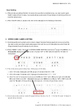
Page 18: ... st Programmable Preset Positions ii 4 6 7 2 When the figure under ADR column displayed OFF the function of Auto Image Tracing Positioning is disabled 5 7 When above three steps finished setting press SAVE button to save the setting value of the speed dome camera When SAVE button is pressed the LCD will be displayed in the following information S a v e O K 5 8 4 6 9 Now the picture in LCD will be ...

Page 19: ...will be tracing positioning the image automatically where the voice coming from 6 2 How to Operate Press MODE button move to SPEED DOME MODE the 3 rd of the MENU the previous settings will be displayed on the LCD press STEP button select mode Save 6 S P E E D D O M E M O D E N o n e B u t t o n V o i c e 7 MIC CHECKING MODE 7 1 After the installation is completed you have to execute the Scan funct...
Page 20: ...R E R R O R CHECKING MIC Delegate 000 999 Chairman 01 10 MIC COUNTER 000 1009 ERROR Under scanning no ID code will be displayed ii During MIC CHECKING MODE chairman and delegate s LCD will also shows the scan status iii After confirming the above operations correctly Press MODE button move to MIC CHECKING MODE the 4th page of the MENU It will be showed as following 7 M I C C H E C K I N G M O D E ...

Page 21: ... the numbers of microphones are increased or reduced please repeat step 7 to scan and then the system will be automatically scanned and detected all the microphones The numbers of microphones and their ID code will be recorded in the system 8 SPEED DOME RETURN 8 1To let camera go back to a default point or not on 5 2 select HGO 8 2 See following for operation Press MODE Move to 8 SPEED DOME RETURN...

Page 22: ... run image override function 9 2 See following for operation Press MODE Move to VIDEO AUTO SWITCH You can see besides Yes Press STEP to choose YES show 1 override image or NO show divided images 9 V I D E O A U T O S W I T C H Y E S N O 9 3 After choosing press SAVE S a v e O K ...

Page 23: ...P A V O I C E 6 0 MIC Volume Mode Settings To Adjust the volume of the microphone connected to the microphone input jack please press the MIC UP button or Down button the LCD will be showed as following After 3 seconds of pressing the button the LCD will be automatically returned to the MENU page and save the settings automatically M I C V O I C E 6 0 AUX Volume Mode Settings To adjust the volume ...

Page 24: ...ndicator lamp of delegate microphones are flashing with RED color once the chairman permits speaking and the ring of LED will be automatically turned to red color without flashing the delegates can speak now 3 The gooseneck microphones are separate with the stand to facilitate the installation repair and maintenance in general condition as well as the transportation storage and assembly 4 The wiri...

Page 25: ...rt flashing with ORANGE color once the 1 st prepared speaker finished speaking the lamps of the 2 nd one will be automatically turned to orange color without flashing and so on 4 The gooseneck microphones are separate with the stand to facilitate the installation repair and maintenance in general condition as well as the transportation storage and assembly 5 Hidden wiring is adopted with Cat 5 cor...

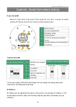
Page 26: ...zation for upgrade Pin 6 Reserved The factory setting of RS 485 is Half Duplex Do not change the setting without the instructions of professional technicians IP Address IP address can be adjusted by the arrow on the switch For example IP address is 123 Please adjust it with the order of Percentile 1 Decile 2 and Unit 3 Please see it as following A Reserved port B Communication Switch C IP Address ...

Page 27: ... make sure 0 Zero is in the north Telecom Protocol Switch No Protocol Baud Rate 00 VCL 9600 01 Pelco D 2400 02 Pelco P 4800 04 Chiper 9600 05 Philips 9600 07 BXB 9600 08 AD422 4800 09 DM P 9600 11 Pelco D 4800 12 Pelco D 9600 13 Pelco P 2400 14 Pelco P 9600 15 JVC 9600 16 GANZ 9600 For example if your protocol is Pelco D the baud rate is 2400 Switch no is 01 and the Setting is as follows ...

Page 28: ...test this IP Speed Dome contains a 50 centimeters data transmission cord Data transmission cord varies depend on the product models DC 12V or AC 24V Please refer to the following pictures Data Transmission Cord DC 12 V Data Transmission Cord AC 24V Power Input 22 Pin connection Video Output 22 Pin connection ...

Page 29: ...of cable is 4000 feet 1219 meters Twisted Pair Cable is recommended BXB Electronics Co LTD TAIWAN Website www bxb tw PA System Conference System Language Laboratory System TEL 886 7 970 3838 FAX 886 7 970 3883 Pin Definition AWG 1 AC24 1 DC GND 20AWG 2 Alarm Pin Not wired 3 AC24 2 DC12 20AWG 4 Alarm Pin Not wired 5 FG 20AWG 6 Alarm Pin Not wired 7 T 24AWG 8 R 9 T 10 R 11 20 Alarm Pin Not wired 21 ...

Reviews: