UK
6
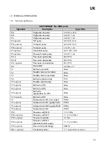
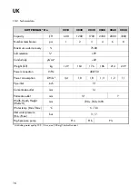
* KMnO4 max: 10 mg/l
If there are doubts about the
raw water composition, a water
analysis must be made. The
plant must be connected to a
water pressure of minimum 3
bar and maximum 7 bar. The
quality of the treated water will
be less than 20 µS/cm at 10 °C.
5.
WATER CONNECTIONS
Note! All water connections
must be in compliance with local
regulations.
For connection of raw water to
the softening unit, see the en-
closed guide on the softening
unit.
5.1
Connection of soft water
to the RO-plant
Connect soft water to the con-
nection on the left side of the
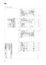
plant on the backside (see encl.
13.2). We recommend connec-
tion with ¾" flexible pressure
hoses. BWT stock complete
assembly kits for the BWT
PERMAQ
®
Pro 2000 series.
The best operating result is ob-
tained by connection to mini-
mum ¾" feed water pipe. In this
way you obtain the necessary
pressure and flow to the plant.
in case of a too small feed water
connection, there will be a risk
of outage on the plant due to
lacking water pressure/amount,
e.g. during flushing of mem-
branes, when the plant is started
up, and a bad function of the
softening plant.
5.2
Connection of permeate
(desalinated water for
consumption)
Connect desalinated water (wa-
ter for consumption) to the water
connection on the reservoir
(option) – the reservoir pump is
recommended connected with
¾" flexible pressure hoses.
Important! Totally desalinated
water can accelerate corrosion,
consequently you should always
use corrosion proof piping for
the treated water, e.g. stainless
steel or PVC pipe.
5.3
Connection of outlet hose
(concentrate)
The outlet valve (concentrate)
shall be fitted with a 14 mm
hose (enclosed). The hose shall
be led to floor drain. (If a bent
piece of hose has been fitted on
the outlet valve, this shall be
removed first).
Important! The outlet pipe must
not be led all the way down into
the water in the floor drain, as
there is then a risk it will get
sucked back into the plant in
case of a stoppage.
Important! It should never be
possible for the outlet hose to
become bent or in any other
way clogged, as it would dam-
age the membrane(s).
6.
ELECTRICAL
CONNECTIONS
Note! The electrical connections
must be made in compliance
with local regulations.
The electrical connection to the
BWT PERMAQ
®
Pro 2000 plant
must be as follows:
*Voltage:
3x400 V+N+PE
*Net:
TN-S
*Frequency: 50 Hz
*Recommended Fuse: 16 Amp
See also electric diagram under
encl. 13.3
7.
START-UP OF THE
PLANT
Read section below carefully
before starting up the plant.
When the plant is started for the
first time, the attached Start-up
test (see Section 13.4) must be
filled and archived together with
Operating Journal (see Section
13.5).
Check before start-up that all
water and electric connec-
tions are made in compliance
with local regulations.
Before start-up the softening
plant (option) shall be adjust-
ed at the current hardness in
the feed water supply and
then commissioned.
Assuming that the softening
plant is now in operation,
check that it supplies soft wa-
ter at the soft-water control
valve (V4). Sampling set is
included in deliveries of new
softening plants (see instruc-
tion manual in the box).
Pull out the permeate hose
from the reservoir tank (op-
tion) and lead it away from
the reservoir to a drain. (This
does not apply to plants with
quality flush (option)).
Open the outlet valve com-
pletely (see encl. 13.7 Pos.
6).
Now switch on the plant
power supply. The plant will
now be operating.
Check that the motor runs in
the right direction.
Now the plant must operate
and flush to drain for 20-30
minutes before re-adjusting
the outlet valve.
After
completed
flushing,
adjust the outlet valve (see
encl. 13.7 Pos. 6 and recircu-
lation valve 13.7 Pos. 1).
7.1
Adjustment of outlet
amount
Important! Read the entire
chapter before adjustment is
started.
The outlet amount must be ad-
justed and which amount is
suitable on your plant depends
on the feed-water quality. Too
high water recovery will dam-
age the plant membranes. On
Summary of Contents for PERMAQ PRO 2000
Page 2: ...UK 2...
Page 11: ...UK 11 Alarm Transport pump 9 2 4 Indication Level low 9 2 5...
Page 19: ...UK 19 13 1 P I Diagram...
Page 20: ...UK 20 13 2 Layout Drawings...
Page 21: ...UK 21 13 3 Wiring Diagram...
Page 22: ...UK 22...
Page 23: ...UK 23...
Page 24: ...UK 24...
Page 28: ...UK 28 13 7 Spare Parts Drawing...

