background image

INSTRUCTION, USE AND 

MAINTENANCE MANUAL

GB

Page 28 of 66

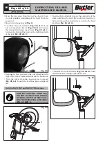
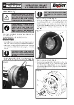
• Keeping the lever pressed, lower the wheel until the 

edge of the rim is approximately 5 mm distant from 
the hook tool.

• Turn the wheel clockwise keeping lever pressed until 

the bead has gone completely out.

• Move away the tool holder arm in “out of work” po-

sition (

Fig.

_

15 ref.

_

1

); lower the mandrel until the 

tyre rests on the movable footboard; exert a certain 
pressure on it so that when the movable footboard 

is moved outwards, this will create enough space to 
extract the inner tube.

• Extract the inner tube and lift the wheel.
• Move to work position 

D

 (

Fig.

_

6

).

• Tilt up tool holder arm, unhook it and lift it placing 

it  in  “off-work”  position  (

Fig.

_

15 ref.

_

1

);  use  the 

handle control to position the tool holder arm on the 
inner side of the wheel then place it in work position 

(

Fig.

_

14 ref.

_

1

) and secure with the coupling lever 

provided (

Fig.

_

1-2 ref.

_

8

).

• Carry out the tools holder head 180° rotation, accord-

ing to the descriptions in the relevant paragraph, in 
order to insert the hook between the rim edge and the 
tyre bead; the operation must be carried out during 
mandrel rotation.

• Move the rim away from the tool by about 4-5 cm 

to  avoid  possible  unhooking  of  the  bead  from  the 
same tool.

• Move to work position 

A

 (

Fig.

_

6

).

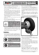
• Translate the hook tool outwards until the reference 

notch is 3 cm inside the rim.

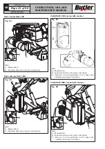
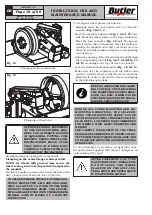
• Insert the lever (

Fig.

_

34 ref.

_

1

) between rim (

Fig.

_

34 

ref.

_

2

) and bead (

Fig.

_

34 ref.

_

3

) on the tool right.

Fig.

_

34

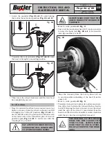
• Keeping the lever pressed, lower the wheel until the 

edge of the rim is approximately 5 mm distant from 
the hook tool then turn the mandrel counterclock-
wise keeping the lever (

Fig.

_

34 ref.

_

1

) pressed until 

the tyre has been completely dislodged from the rim.

THE REMOVAL OF THE BEADS 

FROM THE RIM CAUSES THE 

TYRE TO FALL. ALWAYS MAKE 

SURE THAT NO ONE IS STAND-

ING BY ACCIDENT IN THE WORK 

AREA.

WHEN DEMOUNTING VERY HEAVY 

TYRES, IT IS IMPORTANT TO 

MOVE THE WHEEL AS CLOSE AS 

POSSIBLE TO THE BASE BEFORE 

COMPLETING THE OPERATION.

12.7.3 Mounting

THROUGHOUT TYRE MOUNT-

ING/DEMOUNTING OPERATIONS, 

CHECK THAT THE SELF-CEN-

TRING CHUCK CLAMPING PRES-

SURE IS CLOSE TO THE MAXIMUM 

OPERATING VALUE (150 BAR).

• Secure the rim to the mandrel according to the proce-

dure described in paragraph “WHEEL CLAMPING”.

• Adequately lubricate the tyre beads and the rim bead 

seat  with  a  suitable  lubricant  using  the  provided 
brush.

USE ONLY TYRE LUBRICANTS. 

SUITABLE LUBRICANTS CON-

TAIN NO WATER, HYDROCAR-

BONS, OR SILICON.

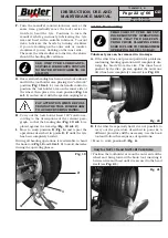
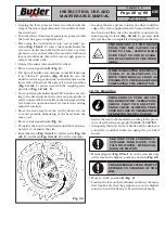
• Mount grippers (

Fig.

_

29 ref.

_

1

) on the external edge 

of the rim in the highest point as shown in 

Fig.

_

29

.

THE GRIPPERS MUST BE TIGHTLY 

SECURED TO THE EDGE OF THE 

RIM.

• Move to work position 

B

 (

Fig.

_

6

).

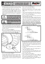
• Position the tyre on the footboard and lower the man-

drel (make sure that the grippers are in the highest 
point) to hook the first tyre bead (internal bead).

7505-M001-3_B

NAV11N - NAV11NT

NAV11EI - NAV11TEI

Summary of Contents for NAV11EI

Page 1: ...he section LIST OF COMPONENTS enclosed to this manual GB TRANSLATION FROM THE ORIGINAL INSTRUCTIONS Rev n 3 01 2017 7505 M001 3_B BUTLER ENGINEERING and MARKETING S p A a s u Via dell Ecologia 6 42047...

Page 2: ...HE MACHINE______________ 18 12 1 Precaution measures during tyre removal and fitting___________________ 18 12 2 Preliminary operations_______________ 18 12 3 Preparing the wheel__________________ 18 1...

Page 3: ...c power unit 5 Self centring chuck 6 Bead breaking disc 7 Tool 8 Coupling lever 9 Tool holder arm 10 Tools unit only for NAV11N 11 Quick fit tool 12 Tools carriage 13 Mandrel rotation motor 14 Mandrel...

Page 4: ...ion with inverter 3 Tools carriage translation cylinder 4 Hydraulic power unit 5 Self centring chuck 6 Bead breaking disc 7 Tool 8 Coupling lever 9 Tool holder arm 10 Tools unit only for NAV11EI 11 Qu...

Page 5: ...ith fork lift truck or pallet truck Lift from above B1541000 General danger Wear safety goggles Technical assistance necessary Do not perform any intervention Risk of crushing and collisions self cent...

Page 6: ...6 of 66 PLATES LOCATION ON MACHINE INFORMATION TABLE 7505 M001 3_B NAV11N NAV11NT NAV11EI NAV11TEI NAV11EI NAV11TEI NAV11N NAV11NT version with inverter NAV11EI NAV11TEI version with inverter NAV11N...
Page 7: ...monophasic version 220V 60Hz 999912700 1 lever distributor plate 999912840 Danger plate 1 999912850 Danger plate 2 999912860 Danger plate 3 999912870 Danger plate 4 999912880 Danger plate 5 999916311...

Page 8: ...f satisfaction 7505 M001 3_B NAV11N NAV11NT NAV11EI NAV11TEI 2 0 INTENDED USE The machines model NAV11N NAV11NT NAV11EI and NAV11TEI with relevant versions are tyre changers with electro hydraulic wor...

Page 9: ...opening of clamping unit jaws Such valves are installed to avoid that accidental oil leakages provoke unwelcome jaws movements and as a consequence the fall of the wheel Fuses on the electric supply l...

Page 10: ...sing the main switch The machine electrical supply system must be equipped with an appropriate earthing to which the yellow green machine protection wire must be connected Ensure that the work area ar...

Page 11: ...ements plastic bags polystyrene foam nails screws wood etc must be collected up and disposed of through according to the in force laws except for the pallet which could be used again for subsequent ma...

Page 12: ...00 Watt as envisaged by UNI 10380 8 0 WORKING ENVIRONMENT CONDI TIONS The machine must be operated under proper condi tions as follows temperature 0 55 C relative humidity 30 95 dew free atmospheric p...

Page 13: ...ate tightening torque of 70 Nm 9 2 Fixtures contained in the packing The packing case contains also the fixtures box Check that all the parts listed are there Code Description N G108A3 Lever with head...

Page 14: ...32 FOR COUNTRIES WITH ROOM TEMPERATURE FROM 0 TO 30 DEGREES VISCOSITY 46 FOR COUNTRIES WITH ROOM TEMPERATURE ABOVE 30 DEGREES 10 2 Check of motor rotation direction Once the last electrical connectio...

Page 15: ...trol Fig 8C VARGNAV11EID version with inverter KEY A Main switch B Rotation direction of power unit motor C Selector 1 0 2 respectively 1 5 10 rpm self centring chuck speed control Fig 8D B A C NAV11N...

Page 16: ...andrel clockwise anti clockwise rotation A B C B C D Fig _9 11 2 Control device only for NAV11N and NAV11NT models with VARGNAV11ND version with inverter This control device consists of 2 units contro...

Page 17: ...one free from obstacles in order to see clearly and completely the operative zone MAKE SURE THERE ARE NO PER SONS OR OBJECTS HIDDEN TO THE OPERATOR VISUAL FIELD BY THE WHEEL SIDE PLAY ESPE CIALLY IN C...

Page 18: ...meter up to 1640 mm and with remarkable weight up to 1500 kg The utmost care while moving the wheels is recom mended make use of other operators properly trained and with suitable clothes DURING ALL T...

Page 19: ...move the footboard towards the mandrel and centre the wheel on it in the most suitable position using the corresponding control levers Adjust the opening of the self centring chuck through the corresp...

Page 20: ...ng to the operations to be performed afterwards before it reaches working position again Fig _16 UNLOCK POSITION CLAMPING POSITION DURING ALL TYRES MOUNTING AND DE MOUNTING OPERATIONS THE SELF CEN TRI...

Page 21: ...ANY PART OF YOUR BODY BETWEEN THE TOOL UNIT AND THE TYRE THROUGHOUT TYRE MOUNT ING DEMOUNTING OPERATIONS CHECK THAT THE SELF CEN TRING CHUCK CLAMPING PRES SURE IS CLOSE TO THE MAXIMUM OPERATING VALUE...

Page 22: ...ng disc Fig _19 ref _1 is placed against the rim edge Fig _19 ref _2 I Move to work position D Fig _6 and repeat the operations described in points E F until the tyre has been completely beaded During...

Page 23: ...of the bead from the same tool Move to work position A Fig _6 Translate the tool outwards Fig _22 ref _2 to al low easy insertion of lever Fig _22 ref _1 between the rim and the bead insert lever Fig...

Page 24: ...REPOSI TIONING THE TOOL HOLDER ARM TO AVOID CRUSHING HANDS ALWAYS MAKE SURE THAT THE ARM IS CORRECTLY HOOKED TO CARRIAGE Move to work position D Fig _6 Carry out the tools holder head 180 rotation in...

Page 25: ...nt using the provided brush USE ONLY TYRE LUBRICANTS SUITABLE LUBRICANTS CONTAIN NO WATER HYDROCARBONS OR SILICON Mount grippers Fig _29 ref _1 on the external edge of the rim in the highest point as...

Page 26: ...the provided brush USE ONLY TYRE LUBRICANTS SUITABLE LUBRICANTS CONTAIN NO WATER HYDROCARBONS OR SILICON Mount grippers Fig _29 ref _1 on the external edge of the rim in the highest point THE GRIPPER...

Page 27: ...RE The beading procedure is the same one described for tubeless tyres WHEN BEADING WHEELS WITH INNER TUBES INTERRUPT THE FORWARD MOVEMENT OF THE BEADING DISC AS SOON AS THE BEADS HAVE BEEN DISLODGED T...

Page 28: ...otch is 3 cm inside the rim Insert the lever Fig _34 ref _1 between rim Fig _34 ref _2 and bead Fig _34 ref _3 on the tool right Fig _34 Keeping the lever pressed lower the wheel until the edge of the...

Page 29: ...hook from the tyre Place the tool holder arm in out of work position Fig _15 ref _1 and translate it to the outer side of the tyre Carry out the tools holder head 180 rotation ac cording to the descri...

Page 30: ...on the platform Move to work position B Fig _6 Check the state of the tyre valve and centre it if neces sary in the rim hole by slightly turning the mandrel fix the valve with the supplied ring nut a...

Page 31: ...y of the inner tube and valve Place the tools holder arm in off work position Fig _15 ref _1 operate the handle control in order to position the tools holder arm on the wheel outer side then place it...

Page 32: ...O ONE IS STANDING BY ACCIDENT IN THE WORK AREA THE REMOVAL OF THE BEADS FROM THE RIM CAUSES THE TYRE TO FALL ALWAYS MAKE SURE THAT NO ONE IS STAND ING BY ACCIDENT IN THE WORK AREA WHEN DEMOUNTING VERY...

Page 33: ...r and other waste materials with a vacuum cleaner DO NOT BLOW IT WITH COMPRESSED AIR Periodically preferably once a month make a complete check on the controls ensuring that they provide the specified...

Page 34: ...rd Fig _46 ref _2 again 1 2 3 4 5 Fig _46 OPERATION TO BE CARRIED OUT ONLY IN CASE THE CARRIAGE MOVES IN A NON LINE AR WAY TRIGGER ACTION B Adjust the play of slide Fig _47 ref _1 by means of the adju...

Page 35: ...t Power drop during wheel holder mandrel rotation a Timing belt too loose a Tension up the belt No pressure in the hydraulic sys tem a Pump damaged a Replace pump The mandrel opening pressure does not...

Page 36: ...en exceeded b The second current threshold has been exceeded c Lack of supply d Insufficient net voltage e Net voltage too high f Sudden and short drop of net voltage g The second temperature thresh o...

Page 37: ...d 8 rpm Max self centring chuck rotation speed VARGNAV11ND and VARGNAV11EID version with inverter 1 5 10 rpm Maximum wheel diameter 1640 mm 64 Wheel max width 925 mm 36 4 Wheel maximum weight 1500 Kg...

Page 38: ...INSTRUCTION USE AND MAINTENANCE MANUAL GB Page 38 of 66 1860 1620 750 1040 1360 max 1640 Fig _48 15 2 Dimensions 7505 M001 3_B NAV11N NAV11NT NAV11EI NAV11TEI NAV11N NAV11NT...

Page 39: ...INSTRUCTION USE AND MAINTENANCE MANUAL GB Page 39 of 66 750 1040 975 max 1640 1795 1485 Fig _49 NAV11N NAV11NT NAV11EI NAV11TEI 7505 M001 3_B NAV11EI NAV11TEI...

Page 40: ...ee 49 14 and subsequent amendments we communicate what follows the meaning of the crossed dustbin symbol reported on the equipment indicates that the product must not be thrown among the undifferentia...

Page 41: ...CHEES LISTA DE PIEZAS Pag 41 di 66 Tavola N A Rev 0 146605510 NAV11N NAV11NT NAV11EI NAV11TEI 7505 M001 3_B SCHEMA ELETTRICO TRIFASE 1 2 THREEPHASE ELECTRICAL SCHEME 1 2 DREIPHASEN SCHALTPLAN 1 2 SCHE...

Page 42: ...oard inverter Main switch Line guard fuse Klemme Spiendel Motor Steuerung Motor Pedalleiste Frequenumformer Schalter general Linieschmelzsicherung Borne Moteur mandrin Moteur distributeur Variateur p...

Page 43: ...ES LISTA DE PIEZAS Pag 43 di 66 Tavola N B Rev 0 750505610 A A Q14 F3 KM1 KM2 T1 K5 F2 F1 K3 K4 K5 F5 VC1 NAV11N NAV11NT NAV11EI NAV11TEI 7505 M001 3_B SCHEMA ELETTRICO 1 7 THREEPHASE ELECTRICAL 1 7 S...

Page 44: ...5mmq 750565131 F3 2A R3 S3 230 400 26V F5 8A F4 2A 26 24 0 00 00 VC1 9 8 24 0 4GX2 5mmq 750565110 M1 U1 V1 W1 R2 S2 T2 4G1 5 mm R2 S2 T2 MOTORE CENTRALINA OLEODINAMICA HYDRAULIC POWER UNIT MOTOR MOTO...

Page 45: ...13 13 13 4 5 6 7 10 11 11 13 21 23 6 7 4 5 9 12 14 22 24 S2 A D E 10 11 S3 MANDRINO SALITA MANDREL LIFTING R S T MANDRINO DISCESA MANDREL DESCENT CARRO UTENSILE AVANTI TOOL CARRIAGE FORWARD CARRO UTEN...

Page 46: ...0 750505610 E A D S3 D E A S2 S5 DETTAGLIO B B DETAIL DETTAGLIO A A DETAIL MOLLA PER LIBERARE I CONTATTI VERSO IL LATO OPPOSTO SPRINGS FOR CONTACTS RELEASE TOWARD OPPOSITE SIDES NAV11N NAV11NT NAV11E...

Page 47: ...IECES DETACHEES LISTA DE PIEZAS Pag 47 di 66 Tavola N B Rev 0 750505610 Q1 Q2 Q3 Q4 Q5 Q6 Q13 NAV11N NAV11NT NAV11EI NAV11TEI 7505 M001 3_B SCHEMA ELETTRICO 5 7 THREEPHASE ELECTRICAL 5 7 SCHALTPLAN 5...

Page 48: ...30 510150 2 2 7 VC1 PONTE RADDRIZZATORE VC1 B1296200 1 2 7 CONDENSATORE C1 C2 B1296300 1 2 7 INS CAVO ALIMENTAZIONE QUADRO 750565110 1 INS CAVO MOTORE MANDRINO 750565121 1 INS CAVO MOTORE CENTRALINA 7...

Page 49: ...3290 1 3 7 REFERENCE DESCRIPTION TECHNICAL SPECIFICATIONS QUANTITY DOCUMENT REFERENCE FUSE HOLDER 10 3x38 32A 690V 3 POLES SECTIONABLE FUSE 10 3x38 16A 500V aM DELAYED TRIPOLAR AUTOMATIC SWITCH FUSE H...

Page 50: ...R INVERTIRE LA ROTAZIONE SCAMBIARE IL FILO n 3 CON IL FILO n 4 IN ORDER TO REVERSE ROTATION EXCHANGE WIRE nr 3 WITH WIRE nr 4 COLLEGAMENTO MOTORE ICME ICME MOTOR CONNECTION COLLEGAMENTO MOTORE CARPANE...

Page 51: ...Klemme Spiendel Motor Steuerung Motor Pedalleiste Frequenumformer Schalter general Linieschmelzsicherung Borne Moteur mandrin Moteur distributeur Variateur p dales de direction Interrupteur general Fu...

Page 52: ...PIECES DETACHEES LISTA DE PIEZAS Pag 52 di 66 Tavola N D Rev 1 750505570 SCHEMA ELETTRICO 1 4 THREEPHASE ELECTRICAL 1 4 SCHALTPLAN 1 4 SCHEMA ELECTRIQUE 1 4 ESQUEMA ELECTRICO 1 4 VARGNAV11ND I1 19752...

Page 53: ...TACHEES LISTA DE PIEZAS Pag 53 di 66 Tavola N D Rev 1 750505570 Q2 Collegamento di terra Ground connection SCHEMA ELETTRICO 2 4 THREEPHASE ELECTRICAL 2 4 SCHALTPLAN 2 4 SCHEMA ELECTRIQUE 2 4 ESQUEMA E...

Page 54: ...750565380 3Gx0 35mm2 750565360 1 2 3 5 4Gx0 35mm2 750565300 3 4Gx1 5mm2 750565390 R S T N R1 S1 T1 N 5Gx4mm2 750565370 u1 v1 w1 F1 M1 M2 I1 Q2 Q3 V1 19709 19694 F2 25A 16A MOTORE MANDRINO MOTORE CENTR...

Page 55: ...M1 MOTORE CENTRALINA 80 4 B14 KW0 75 230 400 50 S1 900002250 1 M2 MOTORE MANDRINO ME 80 B4 KW1 1 185V 50HZ 3PH3 900004800 1 V1 VENTOLA DI RAFFREDDAMENTO 16718 1 ASSIEME IV3K 19752 1 COMPONENTS LIST F...

Page 56: ...HEES LISTA DE PIEZAS Pag 56 di 66 Tavola N E Rev 1 750505560 IG T1 F2 F1 F4 F3 F5 VC1 K3 K4 K5 IV3K IV3K K5 SCHEMA ELETTRICO 1 7 THREEPHASE ELECTRICAL 1 7 SCHALTPLAN 1 7 SCHEMA ELECTRIQUE 1 7 ESQUEMA...

Page 57: ...R2 S2 T2 Q14 518141 F1 515025 3fus 507045 R2 S2 T2 F2 R3 S3 230 400 26V F5 8A 26 00 00 VC1 9 8 M1 U1 V1 W1 N F3 R N F4 R3 N 1 5mm2 N L GND N L GND 2 5mm2 N L GND 19737 V W U GND 1 2 3 4 5 6 7 8 2 5mm...

Page 58: ...S2 A D E 10 11 S3 R S T 6 7 8 MANDRINO SALITA MANDREL LIFTING MANDRINO DISCESA MANDREL DESCENT CARRO UTENSILE AVANTI TOOL CARRIAGE FORWARD CARRO UTENSILE INDIETRO TOOL CARRIAGE BACKWARD APERTURA MAND...

Page 59: ...0 E A D S3 D E A S2 S5 DETTAGLIO B B DETAIL DETTAGLIO A A DETAIL MOLLA PER LIBERARE I CONTATTI VERSO IL LATO OPPOSTO SPRINGS FOR CONTACTS RELEASE TOWARD OPPOSITE SIDES SCHEMA ELETTRICO 4 7 THREEPHASE...

Page 60: ...PIECES DETACHEES LISTA DE PIEZAS Pag 60 di 66 Tavola N E Rev 1 750505560 Q1 Q2 Q3 Q4 Q5 Q6 Q13 SCHEMA ELETTRICO 5 7 THREEPHASE ELECTRICAL 5 7 SCHALTPLAN 5 7 SCHEMA ELECTRIQUE 5 7 ESQUEMA ELECTRICO 5...

Page 61: ...38 8A 500V AM 507100 1 2 7 Q1 Q2 Q3 Q4 Q5 Q6 Q13 7 K3 MORSETTO 2 5mmq C DIODO 1N4007 510218 6 2 7 K4 MORSETTO A MOLLA 2 PIAN 1 5mmq 510217 7 2 7 K5 MORSETTO G V 4mmq ART TEO 4 CABUR T0430 510150 2 2 7...

Page 62: ...1 750516201 750516211 1 1 1 1 1 1 1 S2 517157AS 1 5 7 1 S3 517300 1 5 7 S5 518272 1 5 7 1 T1 100 VA 50 60 Hz PRI 0 400V SEC 0 24V 0 26V 528085 1 2 7 M1 900004670 1 3 7 M2 900003930 1 3 7 REFERENCE DES...

Page 63: ...ECES DETACHEES LISTA DE PIEZAS Pag 63 di 66 Tavola N F Rev 0 750501050 1 2 3 4 4 5 6 6 7 7 NAV11N NAV11NT NAV11EI NAV11TEI 7505 M001 3_B SCHEMA OLEODINAMICO 1 2 HYDRAULIC SCHEME 1 2 LDYNAMISCHPLAN 1 2...

Page 64: ...3 16 oil pressure pipe 3 16 oil pressure pipe 3 16 oil pressure pipe Motorsatz Steuerung Steuerung Elektromotor 220 400V 50 60 Hz 3 Ph 3 16 l Luft Schlauch 3 16 l Luft Schlauch 3 16 l Luft Schlauch 3...

Page 65: ...PIEZAS Pag 65 di 66 Tavola N G Rev 0 750505041 M TARATA 170 BAR 1 2 1 2 3 4 5 5 6 7 8 9 10 11 13 12 14 15 16 17 NAV11N NAV11NT NAV11EI NAV11TEI 7505 M001 3_B SCHEMA OLEODINAMICO 1 2 HYDRAULIC SCHEME 1...

Page 66: ...3 16 l Luft Schlauch L 1670 3 16 l Luft Schlauch L 2900 Zylinder f r ffnung Schlie en des Spindels Zylinder Wagenverschiebung Zylinder f r Spindelsanheben Steuerung Tank Filter Pumpenmotor Pumpe Kalib...

Page 67: ...ARTS TO BE REPLACED THE REPLACEMENT MUST BE CARRIED OUT PROFESSIONALLY QUALIFIED PER SONNEL DIE ZEICHNUNGEN DIENEN NUR ZUR IDENTIFIZIERUNG DER ERSATZTEILE DIE ERSETZUNG MUSS DURCH QUALIFIZIERTES PERSO...

Page 68: ...P DALES DE DIRECTION VERS AVEC INVERSEUR GRUPO COLUMNA PEDALERA VERSI N CON INVERSOR Tavola N 7D Rev 0___750590580 18 GRUPPO COMANDO PER ROTAZIONE A TERRA VAR CON INVERTER CONTROL UNIT FOR GROUND ROTA...

Page 69: ...1 Rev 2 Tav Tab 6 58 56 52 24 Tav Tab 2 3 Tav Tab 4 5 Tav Tab 7A Tav Tab 7B Tav Tab 8 Tav Tab 9 Tav Tab 10 Tav Tab 11 Tav Tab 12 13 62 16 15 15 15 17 18 18 18 19 19 18 19 19 20 21 22 22 21 23 24 25 24...

Page 70: ...750590030 4B 750590200 5A 750590040 5B 750590170 6A 750590050 6B 750590481 7A 750590061 7B 750590421 7C 750590410 7D 750590580 8 750590110 9 750590140 10A 146693010 10B 750503070 10C 750303040 10D 750...

Page 71: ...N 1 Rev 2 630055 20 750510270 21 203035 22 750511460 23 238004 24 203019 25 058135150 26 146610340 27 236006 28 203221 29 750510300 30 146710450 31 226009 32 212172 33 203188 34 750511450 35 203021 36...

Page 72: ...validi per versione monofase 220V 60Hz Parts valid for 220V 60Hz single phase version Teile g ltige f r 220V 60Hz einphasige Version Pi ces valides pour version monophas e 220V 60Hz Piezas v lidos pa...

Page 73: ...25 26 27 28 29 42 30 30 31 31 31 31 32 32 33 34 35 35 35 35 36 40 36 37 38 39 39 39 39 39 39 39 39 39 39 40 36 40 41 41 41 41 42 42 42 30 43 43 43 43 43 42 44 44 45 46 47 48 49 50 51 51 51 52 52 52 5...

Page 74: ...ES PIECES DETACHEES LISTA DE PIEZAS Pag 8 di 27 Tavola N 3 Rev 0 750390641 GRUPPO GRIFFA AUTOCENTRANTE SELF CENTERING JAW UNIT SELBSTZENTRIERENDES KLAUESATZ GROUPE GRIFFE AUTOCENTREURE GRUPO GANCHO AU...

Page 75: ...CARRO UTENSILIO Tavola N 4A Rev 1 750590030 35 32 1 1 1 1 1 2 2 2 2 2 2 2 3 3 3 3 3 3 3 3 4 4 4 4 4 4 4 4 3 2 3 2 3 5 5 5 5 5 5 1 5 6 6 6 6 6 5 6 2 6 6 7 8 8 9 9 10 10 5 6 11 12 13 13 14 14 15 16 17 1...

Page 76: ...CARRO UTENSILIO Tavola N 4B Rev 1 750590200 35 32 1 1 1 1 1 2 2 2 2 2 2 2 3 3 3 3 3 3 3 3 4 4 4 4 4 4 4 4 3 2 3 2 3 5 5 5 5 5 5 1 5 6 6 6 6 6 5 6 2 6 6 7 8 8 9 9 10 10 5 6 11 12 13 13 14 14 15 16 17 1...

Page 77: ...DES PIECES DETACHEES LISTA DE PIEZAS Pag 11 di 27 GRUPPO UTENSILI TOOLS UNIT WERKZEUGSATZ GROUPE OUTILES GRUPO UTENSILIOS Tavola N 5A Rev 1 750590040 1 1 2 3 4 5 6 6 7 8 9 8 9 10 11 12 12 13 14 14 15...

Page 78: ...S Pag 12 di 27 GRUPPO UTENSILI SENZA LEVA TOOLS UNIT WITHOUT LEVER WERKZEUGSATZ OHNE HEBEL GROUPE OUTILES SANS LEVIER GRUPO UTENSILIOS SINE PALANCA Tavola N 5B Rev 0 750590170 22 1 2 3 4 5 6 7 8 9 9 1...

Page 79: ...DETACHEES LISTA DE PIEZAS Pag 13 di 27 GRUPPO MOTORE CENTRALINA MOTOR UNIT HYDRAULIC POWER UNIT MOTORSATZ STEUERUNG GROUPE MOTEUR DISTRIBUTEUR GRUPO MOTOR CENTRALITA Tavola N 6A Rev 1 750590050 1 2 3...

Page 80: ...DETACHEES LISTA DE PIEZAS Pag 14 di 27 GRUPPO MOTORE CENTRALINA MOTOR UNIT HYDRAULIC POWER UNIT MOTORSATZ STEUERUNG GROUPE MOTEUR DISTRIBUTEUR GRUPO MOTOR CENTRALITA Tavola N 6B Rev 0 750590481 3 1 2...

Page 81: ...PIEZAS Pag 15 di 27 GRUPPO COMANDO CONTROL UNIT BEFEHLUNGSATZ GROUPE COMMANDE GRUPO MANDO Tavola N 7A Rev 1 750590061 1 2 3 4 5 6 7 7 8 9 9 10 11 11 12 12 13 13 14 15 16 17 18 18 18 18 18 19 20 20 21...

Page 82: ...E PIEZAS Pag 16 di 27 GRUPPO COMANDO CONTROL UNIT BEFEHLUNGSATZ GROUPE COMMANDE GRUPO MANDO Tavola N 7B Rev 0 750590421 1 2 3 4 4 4 5 6 6 6 6 7 8 8 9 10 10 10 11 12 13 14 15 17 16 18 19 19 22 20 21 21...

Page 83: ...ON INVERTER PEDALBOARD COLUMN UNIT VERSION WITH INVERTER SATZ PEDALLEISTES ULE VERSION MIT INVERTER GROUPECOLONNEP DALESDEDIRECTION VERS AVECINVERSEUR GRUPO COLUMNA PEDALERA VERSI N CON INVERSOR Tavol...

Page 84: ...NVERTER CONTROL UNIT FOR GROUND ROTATION VERS WITH INVERTER BEFEHLUNGSATZF RGEERDETEDREHUNG VERS MITINVERTER GROUPECOMMANDEPOURROTATIONAUSOL VERS AVECINVERSEUR GRUPO MANDO PARA ROTACI N EN TIERRA VERS...

Page 85: ...S PIECES DETACHEES LISTA DE PIEZAS Pag 19 di 27 CILINDRO BRACCIO MANDRINO MANDREL ARM CYLINDER ZYLINDERARM SPINDEL CYLINDRE BRAS MANDRIN CILINDRO BRAZO MANDRIL Tavola N 8 Rev 0 750590110 1 2 3 4 5 6 7...

Page 86: ...STE DES PIECES DETACHEES LISTA DE PIEZAS Pag 20 di 27 CARRELLO PORTAGOMMA HOSE NIPPLE CARRIAGE SCHLAUCHHALTERWAGEN CHARIOT RACCORD PORTE TUYAU CARRO PORTA GOMA Tavola N 9 Rev 0 750590140 1 2 2 3 3 4 4...

Page 87: ...S DETACHEES LISTA DE PIEZAS Pag 21 di 27 MTG CASSETTA ELETTRICA ELECTRICAL BOX MTG MTG ELEKTRISCHEKISTE MTG BOITER LECTRIQUE MTG CAJITA ELECTRICA Tavola N 10A Rev 1 146693010 1 2 3 4 5 6 7 8 9 10 11 1...

Page 88: ...ES LISTA DE PIEZAS Pag 22 di 27 QUADRO ELETTRICO ELECTRIC CABINET SCHALTTAFEL TABLEAU LECTRIQUE CUADRO EL CTRICO Tavola N 10B Rev 0 750503070 1 28 29 27 3 3 4 2 2 2 4 6 19 7 8 8 10 9 11 13 13 14 16 17...

Page 89: ...E DES PIECES DETACHEES LISTA DE PIEZAS Pag 23 di 27 QUADRO ELETTRICO MONOFASE MONOPHASE ELECTRIC CABINET EINPHASEN SCHALTPULT TABLEAU LECTRIQUE UNIPHAS CUADRO EL CTRICO MONOF SICO Tavola N 10C Rev 0 7...

Page 90: ...WITH INVERTER SATZ MTG ELEKTRISCHEKISTE MIT INVERTER ASSEMBLAGE MTG BOITIER LECTRIQUE AVEC INVERSEUR CONJUNTO MTG CAJITA ELECTRICA CON INVERSOR Tavola N 10D Rev 1 750590640 18 85 19 3 12 13 9 8 C D 1...

Page 91: ...LECTRIQUES MTG VERSION AVEC INVERSEUR CAJITAS EL CTRICAS MTG VERSI N CON INVERSOR Tavola N 10E Rev 1 750590720 28 4 3 400V 50Hz 3Ph N 400V 50Hz 3Ph N 46 46 47 47 A A 2 2 1 5 7 6 6 37 38 40 39 35 40 3...

Page 92: ...PIECES DETACHEES LISTA DE PIEZAS Pag 26 di 27 INSIEME PISTONE CARRELLO CARRIAGE PISTON ASSEMBLY WAGENKOLBE SATZ ASSEMBLAGE PISTON CHARIOT ENSAMBLADO PIST N CARRO Tavola N 11 Rev 0 146701010 8 10 1 2...

Page 93: ...ELISTE LISTE DES PIECES DETACHEES LISTA DE PIEZAS Pag 27 di 27 RULLO STALLONATORE BEAD BREAKING ROLL ABDR CKWALZE ROULEAU D COLLE TALONS RODILLO DESTALONADOR Tavola N 12 Rev 0 750590360 1 2 3 4 5 5 75...

Reviews: