


INSTRUCTION, USE AND
MAINTENANCE MANUAL
GB
Page 21 of 66
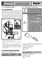
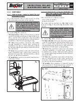
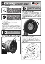
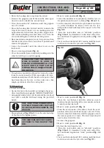
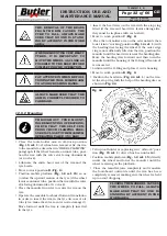
12.5.1 Tools rotation
THE FOLLOWING OPERATIONS
MUST BE CARRIED OUT WITH
THE TOOLS HEAD IN “OFF- WORK”
POSITION.
The machine is equipped with a Quick-fit tool, remark-
ably facilitating the tools unit rotation operations. Here
follows the description of these operations.
In order to rotate the tool head (
Fig.
_
17 ref.
_
1
) just
push the unlocking lever (
Fig.
_
17 ref.
_
3
) towards
the tool arm (
Fig.
_
17 ref.
_
2
). When the new working
position of the head is reached (
Fig.
_
17 ref.
_
1
) the
lever (
Fig.
_
17 ref.
_
3
) automatically inserts locking
its rotation.
2
3
180°
1
Fig.
_
17
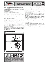
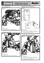
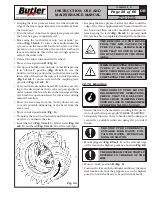
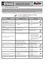
12.6 Tubeless tyres
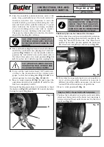
12.6.1 Bead breaking
NEVER PLACE ANY PART OF YOUR
BODY BETWEEN THE TOOL UNIT
AND THE TYRE.
THROUGHOUT TYRE MOUNT-
ING/DEMOUNTING OPERATIONS,
CHECK THAT THE SELF-CEN-
TRING CHUCK CLAMPING PRES-
SURE IS CLOSE TO THE MAXIMUM
OPERATING VALUE (150 BAR).
A.
Lock the wheel on the mandrel as described in the
previous paragraph.
B.
Remove all balancing weights from the rim. Extract
the valve and let air out of tyre.
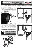
C.
Move to work position
C
(
Fig.
_
6
).
D.
Lower tool holder arm into work position (coupling
lever introduced, see
Fig.
_
16
).
ALWAYS MAKE SURE THAT THE
ARM IS CORRECTLY HOOKED TO
CARRIAGE.
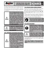
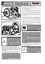
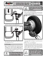
E.
Place as shown in
Fig.
_
18
the beading disc (
Fig.
_
18
ref.
_
1
) by means of the relevant handle control; the
outer profile of the rim (
Fig.
_
18 ref.
_
2
) must almost
touch the beading disc.
Fig.
_
18
3
2
1
THE BEADING DISC MUST NOT
EXERT PRESSURE ON THE RIM
BUT ON THE TYRE BEAD.
NAV11N - NAV11NT
NAV11EI - NAV11TEI
7505-M001-3_B