INSTRUCTION, USE AND
MAINTENANCE MANUAL
GB
Page 20 of 66
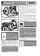
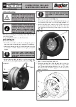
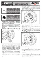
In “out of work” position (
Fig.
_
15 ref.
_
1
): the tool
holder arm is in vertical position and has to be brought
in this position every time it is not in use and in order
to be shifted from one tyre bead side to another, dur-
ing working phase.
1
Fig.
_
15
The tool holder arm, shifts from “off-work” position to
“working” position and vice versa manually.
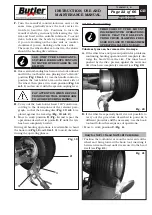
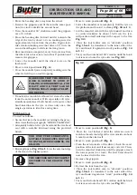
IN WORKING POSITION, THE
COUPLING LEVER (FIG. 1 REF. 8)
MUST BE CORRECTLY HOOKED
HOOKED TO THE TOOL CAR-
RIAGE CLAMPING PROFILES (SEE
FIG. 16).
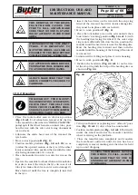
When the tool holder arm is in “off-work” position, it
can be laterally shifted in manual mode in one of the
two pre-set positions on the carriage, so that it can
better positioned (according to the operations to be
performed afterwards) before it reaches “working”
position again.
Fig.
_
16
UNLOCK
POSITION
CLAMPING
POSITION
DURING ALL TYRES MOUNTING AND DE-
MOUNTING OPERATIONS, THE SELF-CEN-
TRING CHUCK ROTATION SPEED CAN BE
DOUBLED BY ROTATING THE SELECTOR (FIG.
8C-8D REF. C). LOW SPEED IS RECOMMENDED
FOR WHEELS WITH GREAT DIAMETER AND
WEIGHT.
THE CAREFUL LUBRICATION OF THE TYRES
BEADS IS RECOMMENDED, IN ORDER TO PRO-
TECT THEM FROM POSSIBLE DAMAGES AND
TO FACILITATE MOUNTING AND DEMOUNTING
OPERATIONS.
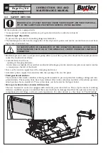
12.5 Functioning of tool holder arm
During the working phases, the tool holder arm can
maintain two firm positions, that is:
1) “Working” position;
2) “Out of work” position.
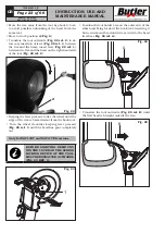
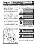
In “working” position (
Fig.
_
14 ref.
_
1
) the tool holder
arm is lowered towards the mandrel and from this
position it executes the various tyre bead breaking,
demounting and mounting operations.
1
Fig.
_
14
7505-M001-3_B
NAV11N - NAV11NT
NAV11EI - NAV11TEI

