OPERATION
l
MAINTENANCE
907
$4.00
50057987
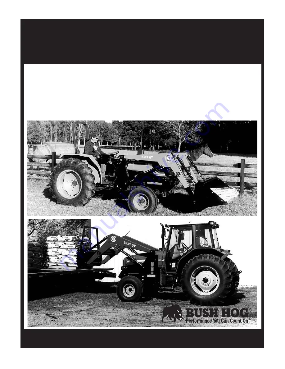
2427, 2447, 2847 & 3227QT
Front End Loaders
Operator’s Manual
BUSH HOG
®
Page 1: ...OPERATION l l MAINTENANCE 907 4 00 50057987 2427 2447 2847 3227QT Front End Loaders Operator s Manual BUSH HOG...
Page 2: ...er we stock genuine Bush Hog parts which are manufactured with the same precision and skill as our original equipment Our trained service personnel are well informed on methods required to service Bus...
Page 3: ...instructions and safety procedures Failure of the operator to read the Operator s Manual is a misuse of this equipment It is the Retail Customer and or Operator s responsibility to inspect the produc...
Page 4: ...Hog duty taxes charges for normal service or adjustment loss of crops or any other loss of income rental of substitute equipment expenses due to loss damage detention or delay in the delivery of equi...
Page 5: ...s appropriate attachments for loader operations Buckets for lifting loose materials bale spear for lifting round bales fork lift for lifting palletized material o Operators manual has been delivered t...
Page 6: ...he tractor at low speeds 7 Stop tractor engine place transmission in park or neutral engage parking brake lower loader arms to ground cycle all hydraulic controls to relieve pressure allow machine mov...
Page 7: ...rly small children The operator should cease operation whenever anyone comes within the operating area 5 Operate the loader from the Operator s Seat Only 6 Exercise caution when operating the loader w...
Page 8: ...not limited to instructions to Keep all guards in place when the machine is in operation Permit no riders on equipment Stop engine disconnect the power source and wait for all machine movement to stop...
Page 9: ...wheel and four wheel drive tractors They come equipped with parking stands to support the loader so the tractor can be driven in for quick attachment and a bucket level indicator that allows operator...
Page 10: ...3020 lbs 2390 lbs 3105 lbs 3360 lbs Forward of Pivot Pin Y Breakout Force At Pivot Pin 4985 lbs 3955 lbs 5030 lbs 5160 lbs Z Breakout Force 31 5 Forward of Pivot Pin 3500 lbs 2940 lbs 3630 lbs 3730 lb...
Page 11: ...B Add rear wheel weights fluid in tires or equiv alent to provide sufficient tractor stability C It is recommended that tractor wheels be moved to the widest settings D Check tractor hydraulic oil re...
Page 12: ...Pin F Extend bucket cylinder dump until subframe rest on rear bracket G Install cuff per Figure 2 4 as shown for model loader being mounted H Tighten nut retaining cuff to 100 ft lbs I Raise boom rem...
Page 13: ...control valve operates as shown on decal If valve operation is incorrect see plumbing diagrams for correct connections 12 Cylinder Mounting Bushing AIR IN HYDRAULIC COMPONENTS WILL CAUSE ERRATIC LOADE...
Page 14: ...F Loosen nut securing cuffs to loader subframe Remove pin securing cuff Remove cuff Figure 2 4 Pin SECTION III OPERATING INSTRUCTIONS 3 1 GENERAL SAFETY Only qualified people familiar with this operat...
Page 15: ...rial loaded in a given period of time Time is lost if two or more attempts are made to fill the bucket on each pass LIFTING THE LOAD WARNING DO NOT LIFT OR CARRY ANYONE IN THE BUCKET OR ON ANY OTHER P...
Page 16: ...HILLSIDE IS DANGEROUS EXTREME CARE IS RECOMMENDED DO THIS NOT THIS When transporting the load keep the bucket as low as possible to avoid tipping in case a wheel drops in a rut NOT THIS DO THIS DUMPIN...
Page 17: ...DING FROM A BANK Choose a forward gear that provides sufficient ground speed for loading Exercise caution when undercutting high banks Dirt slides can be dangerous Load from as low as possi ble for ma...
Page 18: ...cise cut LOADING LOW TRUCKS OR SPREADERS FROM A PILE For faster loading minimize the angle of turn and length of run between pile and spreader Backgrade occasionally with a loaded bucket to keep the w...
Page 19: ...ng the tractor H H Possibility of the object rolling or sliding down the loader arms onto the operator Long Spear Round Bale 18 3 3 BALE SPEAR OPERATION The bale spear Figure 3 2 is intended for handl...
Page 20: ...uff on attachment and lift off ground using boom cylinders only Tilt quick hitch backward so that bottom of attach ment will swing into position Release spring loaded pins into place behind hitch lug...
Page 21: ...ll include the components current safety decals specified by the manufacturer to be affixed to the component 3 Store loader in a dry place THE LOADER CAN FALL FROM HYDRAULIC SYSTEM FAILURE TO AVOID SE...
Page 22: ...rious injury The Bush Hog control valve is pre set at the factory and should not be adjusted 4 4 TROUBLESHOOTING Troubleshooting procedures are listed in Table 4 1 If the problem cannot be solved or r...
Page 23: ...is greater Check loader specifications than boom lift capacity Check tractor system Internal boom cylinder leakage Replace any worn parts and install a seal repair kit Improper hydraulic valve Repair...
Page 24: ...king devices or guards are in place 12 Before operating the machine thoroughly read the operation section of this manual 13 Before operating read the maintenance section of this manual to be sure that...
Page 25: ...2 NPT to 3 4 JIC 3 4 16 JIC Threads 4 Hoses Mainframe To Tractor Outlets Through Quick Couplers Not Supplied 24 Figure 5 3 Cuff Arrangements NOTE HOSES COMING FROM MAINFRAME ARE COLOR CODED FOR IDENTI...
Page 26: ...unting tube to bracket using 1 2 x 3 bolts lockwashers and nuts The slotted hole also requires a flatwasher as shown D Attach valve plate to tube using U bolts lock washers and nuts Note Mounting tube...
Page 27: ...IC Attach Quick Couplers to these fittings Quick couplers not supplied in kit 26 NOTES 1 When attaching a loader valve to the rear remotes of the tractor a power beyond kit is not required Figure 5 6...
Page 28: ...WILL CAUSE SERIOUS DAMAGE TO TRACTOR HYDRAULIC SYSTEM Power Beyond Plug To Pressurized Return Inlet To Sump Inlet Use Long Hose Here To Pressure Inlet B C A These hoses to be furnished by dealer 5 4 B...
Page 29: ...s and lower pins to lock forks in place Mainframe Fork Eccentric Nut Frame Assembly Long Spear Short Spears 28 5 6 BALE SPEAR OPTION Insert long spear into top of frame and fasten with eccentric nut a...
Page 30: ...tting edges on bolts in side plates if necessary 3 Remove spill guard and drill 9 16 holes Install spill guard and torque fasteners per Bush Hog standards SPILL GUARD 9 16 Holes 7Places 1 2 x 1 1 2 Bo...
Page 31: ...Hog will upon request provide safety decals for any of our products in the field at no charge Contact your authorized Bush Hog dealer for more information REAR VIEW OF SUBFRAME Decals 25H46070 25H460...
Page 32: ...4 12 UNF 553 749 1241 1682 2013 2728 2 1 16 1 3 8 6 UNC 655 887 1470 1992 2382 3228 2 1 16 1 3 8 12 UNF 746 1011 1672 2266 2712 3675 2 1 4 1 1 2 6 UNC 870 1179 1950 2642 3161 4283 2 1 4 1 1 2 12 UNF 9...
Page 33: ...P O Box 1039 l l Selma AL 36702 1039 Telephone 334 874 2700 l l www bushhog com...