Advanced settings
7.8.9 Input/Output menu
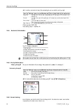
From the "Settings" screen, press
[Advanced] [Input/Output]
.
7.8.10 Input/Output: Serial Link 1 and Serial Link 2
The operator must allocate the 2 serial links (1 and 2) according to their use.
(1)
Accessory
Parameters
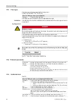
From the "Settings" screen, press
[Advanced] [Input/Output] [Serial Link 1]
or
[Se
rial Link 2] [Parameters]
.
From the "Settings" screen, press [Advanced] [Input/Output], then [Serial Link 1] or [Serial
Link 2].
Type
Set the type of serial link: see table below.
Parameters
Set the serial link mode: see detail below.
Use
Possible allocation
Type to select
Serial Link 1
Serial Link 2
RS-232
yes
no
Serial
USB
yes
yes
USB
Wireless remote control
(1)
yes
no
Serial
Mode
Description
Use
RS-232
USB
Basic
Continuous acquisition of data sent to the hyperterminal according to a defined time duration.
At any time, a command can be sent to the leak detector.
Recommended mode during leak detector test procedure setting operations.
x
x
Spreadsheet
Variant on the Basic mode.
Continuous data acquisition, formatted in a spreadsheet such as Excel Microsoft ® Office or other
similar software.
Recommended mode for drawing graphs.
x
x
Advanced
Full control of the detector by a supervisor.
The detector sends information at the supervisor's request.
5 V power supply available.
Recommended mode for automatic systems.
x
x
Export Data
Export, via a PC, of "tickets" issued by the detector after:
• Calibration with an internal/external calibrated leak,
• Calibration control with an internal leak,
• A test.
Serial links 1 and 2 must not be in “Export Data” mode at the same time.
x
x
(1) See Wireless remote control operating instructions for more details.
70
0870231897_0001_IM_en
Summary of Contents for 0659230708
Page 79: ...Note 79 0870231897_0001_IM_en...

