6.1.
5
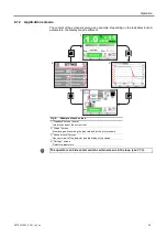
"Graph" screen
Monitoring and recording the leak rate and/or the inlet pressure.
6.1.
6
"Vacuum circuit" screen
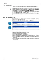
Vacuum circuit of the detector and the status of the valves.
Vacuum circuit is specific for each leak detector.
The vacuum circuit varies depending on the status of the valves, but does not make it
possible to manage the valves.
Fig.
8
:
Example
6.1.
7
"Measurement" window
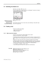
Press the
[Measure]
key to display the window.
Press and drag the window to move it on the screen.
Red valve
Valve closed
Green valve
Valve open
Pumps, Analyzer cell
Press the component to display the operating principle.
Fig.
9
: [Measure] key and corresponding window
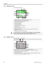
1 Digital display of the leak rate (green
≤
reject set point < red)
2 Detector test mode
3 Error information indicator
4 Zero function indicator
5 Leak rate correction function indicator
2 3 4 5
1
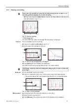
Fig.
7
:
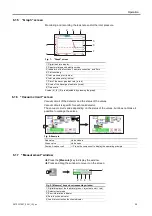
"Graph" screen
Scales (6), (8), (9) are adjustable by pressing the graph.
1 Digital leak rate display
2 Detector status and detection mode
3 Indicators of the functions ’Leak rate correction’ and ’Zero’
4 Plot recording
5 Inlet pressure plot (in blue)
6 Inlet pressure scale (in blue)
7 Plot of the tracer gas leak rate (in red)
8 Scale of the tracer gas leak rate (in red)
9 Time scale
1
2
3
4
8
6
7
5
9
25
0870231897_0001_IM_en
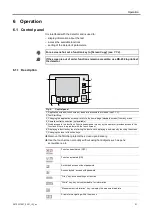
Operation
Summary of Contents for 0659230708
Page 79: ...Note 79 0870231897_0001_IM_en...

