Burster DIGIFORCE 9311 Operation Manual Download Page 134


134

 of 216 


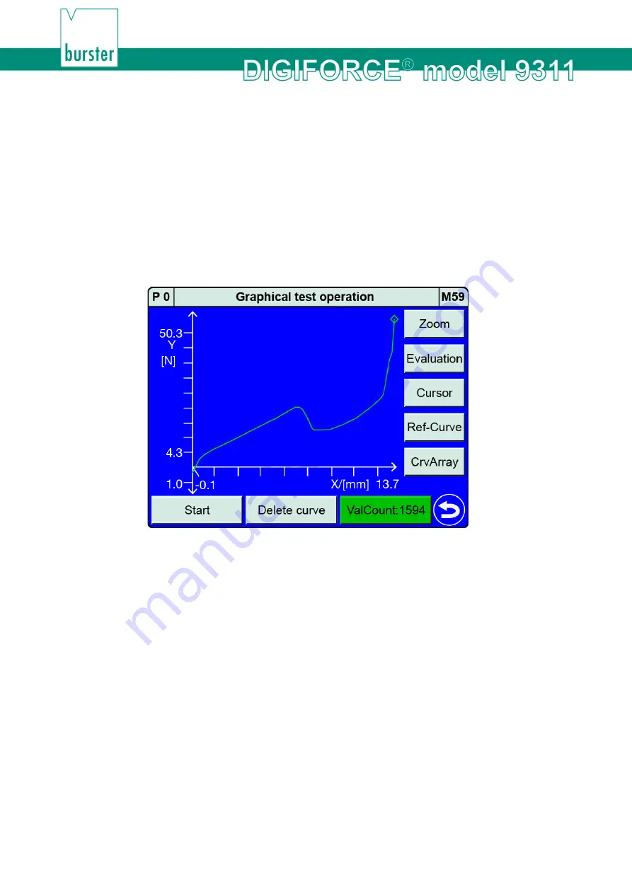
6.3.5  Graphical test operation 

In the "Graphical test operation" menu (M59) you can perform measurements in one or more 

measurement programs and use the recorded measurement curve(s) to define the graphical evaluation 

elements such as "Window", "Trapezoid", "Threshold" and "Envelope". The 10 most recent measurement 

results from each measurement program are saved. You can select 

[CrvArray] 

to display this set of 

recorded measurement curves as a curve array. When calculating an envelope, the DIGIFORCE

®

 9311 

uses these measurement curves as the basis for generating the "Envelope".  

Note: 

Note that on activation of the "IN_AUTO" control input, the "Graphical test operation" menu 

(M59) will close automatically and the DIGIFORCE

®

 9311 will switch to measurement mode. In 

"Graphical test operation", the other PLC I/O control signals respond in exactly the same way as 

in measurement mode, and the online switching points are also active.  


Diagram 57:  Graphical test operation 

The following functions are available in the "Graphical test operation" menu (M59): 

  Run measurements 

  Adjust the scale of the measurement curve 

graph 

[Zoom]


  Configure evaluation elements 

[Evaluation]


  Take readings from the measurement 

curve using the 

[Cursor]


  Enable a measurement curve as the 

reference curve 

[Ref-Curve]


  Show/Hide the curve array view 

[CrvArray]


  External control (start measurement, 

change program, tare, sensor test, ...) 


Summary of Contents for DIGIFORCE 9311

Page 1: ...stechnik gmbh co kg burster praezisionsmesstechnik gmbh co kg All rights reserved Talstr 1 5 P O Box 1432 76593 Gernsbach 76587 Gernsbach Germany Germany Valid from 13 08 2018 Tel 49 7224 645 0 Fax 49...

Page 2: ...nctioning of these products covering material and production defects for the period specified in the warranty document accompanying the product However burster waives any guarantee or warranty obligat...

Page 3: ...3of 216...

Page 4: ...13 2 6 Contents of pack 13 2 7 Unpacking 14 2 8 Warranty 14 2 9 Conversions and modifications 14 2 10 Error messages when the unit is powered up 15 3 Principles of design and operation 16 3 1 Range of...

Page 5: ...ith sense leads 34 4 6 3 4 Connector B connecting strain gage sensors with sense leads fitted with burster TEDS 35 4 6 3 5 Connector B connecting standard signal sensors 35 4 6 3 6 Connector B connect...

Page 6: ...tion 101 6 3 2 Measurement mode 106 6 3 2 1 Sampling the measurement channels 107 6 3 2 2 Measurement curve reference 107 6 3 2 3 Curve recording return point 112 6 3 2 4 Start Stop mode 113 6 3 3 Con...

Page 7: ...measurement mode 188 7 2 M1 Graphical measurement curve 189 7 3 M2 General curve data 190 7 4 M3 Total result 191 7 5 M4 Entry Exit 192 7 6 M5 User defined values 192 7 7 M6 Statistics 193 7 8 M7 Orde...

Page 8: ...nt 207 8 5 3 Example of an OK evaluation without acknowledgement 208 8 6 External actuation of a statistics reset 209 8 7 External actuation of a sensor test 210 9 Customer Services for your DIGIFORCE...

Page 9: ...ided will result in death or serious injury WARNING Moderate degree of risk indicates a hazardous situation which if not avoided may result in death or serious injury CAUTION Low degree of risk indica...

Page 10: ...opening Follow safety instructions Professional servicing only Warning To prevent electrical shock do not open device Warning of electrical shock hazard Do not open the unit To prevent fire replace o...

Page 11: ...department For repair inquiries please telephone our Service department on 49 7224 645 53 or email service burster com Germany only If you are outside Germany you should contact your burster agent see...

Page 12: ...mperature to 50 at Tmax no condensation Class of protection 1 Transient overvoltage category CAT II Potential with respect to ground 12 VDC between analog ground and ground Supply voltage 100 to 240 V...

Page 13: ...cloth to clean the instrument 2 5 Personnel Personnel must be familiar with the relevant regulations They must follow these regulations Only trained personnel who are familiar with the applicable safe...

Page 14: ...following when sending the instrument in for repair If there is a problem with the device please attach a note to the instrument case summarizing the fault Technical specifications subject to change a...

Page 15: ...se call our Service department on 49 07224 645 53 or email service burster com Germany only If you are outside Germany you should contact your burster agent see also www burster com Please refer to th...

Page 16: ...tion results on the colour display and outputs this data at the external control interfaces A powerful real time operating system optimizes processes in the DIGIFORCE 9311 to achieve an extremely fast...

Page 17: ...9311 can process signals from a huge range of sensor technologies Note The Channel settings menu M21 is where the physical connectors and hence the particular sensors are assigned to the measured cur...

Page 18: ...is met Then the DIGIFORCE 9311 immediately evaluates the recorded measurement curve In this evaluation the DIGIFORCE 9311 checks whether the measurement curve satisfies all the defined graphical evalu...

Page 19: ...Sampling the measurement signals 3 5 3 Defining an X axis reference A measurement curve recorded by the DIGIFORCE 9311 can be based on a choice of references For instance for a force displacement cur...

Page 20: ...it sides online signal entry exit min max value 3 X or Y trapezoid configurable entry exit side 2 X or Y threshold configurable crossing 2 Envelope configurable entry exit side 1 3 7 Tare function The...

Page 21: ...assigning a switching signal to the X channel you can choose to refer the set level threshold value to the absolute zero point Absolute reference or to a relative zero point Trigger reference These s...

Page 22: ...se it displays the live sensor values from all active measurement channels You can also use this menu for calibrations based on static measured values In addition the menu displays the digital PLC I O...

Page 23: ...chscreen display 2 User definable function keys F1 to F3 3 Settings Configuration Main Menu 4 Front panel USB service port Note You can choose to have the function keys and the icon displayed permanen...

Page 24: ...ieldbus ports optional 9 PLC I O signals 10 A standard analog connection potentiometer standard signal 11 B standard analog connection strain gage standard signal or piezoelectric input optional 12 Re...

Page 25: ...the touchscreen to perform control actions Touch control options Action Description Symbol used in the operation manual Tap the relevant point on the touchscreen with your finger Swipe your finger do...

Page 26: ...tton to close the selection menu OK Use this button to enter the data you have entered via the keypad Use these buttons to increment decrement any settings Checkbox enabled disabled Radio button enabl...

Page 27: ...length of cable When using mains leads from other manufacturers or an international mains connection you must ensure that there is a proper connection to earth We strongly recommend the following Use...

Page 28: ...CE 9311 at the 25 pin D SUB port The signals are isolated from the controller core and work with positive logic An external 24 VDC supply is needed to operate the PLC outputs the DIGIFORCE 9311 does n...

Page 29: ...oded 9 IN_PROG1 No Bit 1 of measurement program no binary coded 10 IN_PROG2 No Bit 2 of measurement program no binary coded 11 IN_AUTO No DIGIFORCE 9311 is kept in measurement mode 12 IN_PROG3 No Bit...

Page 30: ...signed for this excitation voltage Diagram 9 Connector A PIN Assignment 1 excitation for potentiometer 2 sense 3 not used 4 sense 5 excitation for potentiometer 6 signal input 7 burster TEDS 1 Wire EE...

Page 31: ...etric sensors fitted with burster TEDS You can connect potentiometric sensors fitted with burster TEDS to connector A Connector A looking towards instrument rear socket Diagram 11 Connector A potentio...

Page 32: ...ng standard signal sensors fitted with burster TEDS You can connect standard signal sensors to connectors A and B Connector A looking towards instrument rear socket Diagram 13 Connector A standard sig...

Page 33: ...t are designed for this excitation voltage Diagram 14 Connector B PIN Assignment 1 excitation for strain gage 2 sense 3 not used 4 sense 5 excitation for strain gage 6 signal input 7 burster TEDS 1 Wi...

Page 34: ...B Connector B looking towards instrument rear socket Diagram 16 Connector B strain gage sensors without sense leads fitted with burster TEDS 4 6 3 3 Connector B connecting strain gage sensors with se...

Page 35: ...the 1 Wire signal has to be connected when using an extension cable 4 6 3 5 Connector B connecting standard signal sensors You can connect standard signal sensors to connectors A and B Connector B lo...

Page 36: ...piezoelectric sensors to connector B standard BNC socket Connector B looking towards instrument rear socket Diagram 21 Connector B piezoelectric sensor option Note For this function your DIGIFORCE 93...

Page 37: ...mend using this USB service port for a short period only 4 6 5 Ethernet port You can use the Ethernet port to configure all the settings for the DIGIFORCE 9311 and to retrieve all the measurement and...

Page 38: ...he PROFIBUS interface are provided in a separate document The DIGIFORCE 9311 PROFIBUS manual 4 6 8 Ethernet based Fieldbus interface dual RJ45 Details of the available Ethernet based Fieldbus interfac...

Page 39: ...pecified in this operation manual 5 1 Panel mounting NOTICE Excessive tightening torque may result in damage Overtightening may damage the mounting section Use the screws supplied to cut the thread In...

Page 40: ...tion A DIGIFORCE 9311 B Case cutout C Self adhesive feet remove before fitting D Instrument panel E Mounting sections x4 F Self tapping Torx screws x4 M4x20 5 1 2 Panel cutout Diagram 25 Panel cutout...

Page 41: ...ch 2 After a short boot up phase the self test starts running During the self test if you wish to set the user language then tap either Config or the flag in the top right corner to open the diagnosti...

Page 42: ...Menu Note You can choose to display the icon permanently in measurement mode For further details please see section 6 1 1 Function key definition on page 44 Menu structure Diagram 26 The DIGIFORCE 931...

Page 43: ...setup menu M18 Function key definition PLC outputs PLC inputs Access authorisation Measurement menus Info LCD settings Date and time Language Interfaces Acknowledge function Order sheet USB flash Cha...

Page 44: ...easurement mode Program Switch to the previous program in measurement mode Tare X Tare the X channel Tare Y Tare the Y channel Start Stop Start a measurement Stop a measurement Acknowledge OK parts Ac...

Page 45: ...hat you want to assign 6 Select the function you wish to assign then confirm with ENTER 7 If you want to change how long the function keys are displayed tap Display mode If Always on is enabled then t...

Page 46: ...ROG3 Bit 3 of echoed measurement program number OUT_MEAS_ACT Measurement in progress measurement active OUT_S3 Switching signal S3 OUT_S4 Switching signal S4 OUT_S5 Switching signal S5 OUT_S6 Switchin...

Page 47: ...Tap the Basic setup icon 4 Tap the PLC outputs icon 5 To open the second page of the menu tap the bottom of the scroll bar 6 Tap the name of the pin that you wish to reassign 7 Select the signal that...

Page 48: ...Y Tare the X channel and Y channel IN_RES_STAT Reset the statistics IN_STEST Run the sensor test IN_TEST_OP Switch to Graphical test operation measurement evaluation without counter IN_ACK Acknowledg...

Page 49: ...M39 Define change a master password Define change a user password Enable disable password protection Specify access levels for master user Blocking unblocking access by DigiControl PC software Factory...

Page 50: ...on Switching points Test Operation Sensor test User defined values USB flash 1 After entering the master password tap Password protection to enable this option 2 Tap Access levels 3 Select the access...

Page 51: ...rder sheet 1 In measurement mode tap anywhere on the touchscreen The icon appears in the bottom right corner 2 Tap to open the Configuration Main Menu 3 Tap the Basic setup icon 4 Tap the Measmnt menu...

Page 52: ...of the menu tap the bottom of the scroll bar 6 Tap Station name and enter the name you require via the keypad 7 Tap OK 8 Tap Reset statistics all programs to reset the statistics for all programs Tap...

Page 53: ...p to return to the Basic setup menu 6 1 9 Language In the Language selection menu M60 you can set the user language for the DIGIFORCE 9311 The following 6 languages are available German English French...

Page 54: ...e interface USB or Ethernet for which you want to specify the interface parameters then make the required settings 7 Tap to return to the Basic setup menu 6 1 10 1 USB interface parameters A PC detect...

Page 55: ...btain a valid address from your network administrator Connections to other networks can be made via the gateway Port This is where you select the UDP port default 7292 Note If a firewall is used the U...

Page 56: ...nt the PLC output OUT_ACK_NOK is set to active stops flashing and the buzzer output is deactivated OUT_ACK_LOCK Lock output e g to be used externally to prevent a return stroke OUT_ACK_ALARM If the ac...

Page 57: ...ata logging on a USB flash drive is enabled a data entry containing result data but not the measurement curve is made for each measurement If you have connected a USB flash drive to the rear USB port...

Page 58: ...the file If not a new file is created If the file reaches the maximum file size of 25 MB data is automatically written to a new file Storage location Data YYYY MM Key YYYY year MM month File type csv...

Page 59: ...ce Serial number Serial number of the DIGIFORCE 9311 Component Component name if given in the order sheet Meas Prog Name Name of the measurement program Meas Prog No Number of the measurement program...

Page 60: ...graphical evaluation elements in one measurement program In measurement mode the individual evaluation results indicate the associated element see section 7 1 4 Individual evaluation status in measur...

Page 61: ...set see section 6 3 8 User defined values on page 173 Delimiting character I 0x7C hex Terminating character Line Feed LF 0x0A hex Note If you require an example of a USB stick data logging file please...

Page 62: ...r 2 Tap to open the Configuration Main Menu 3 Tap the Basic setup icon 4 Tap the Channel Setup icon 5 Tap Channel Setup to switch between program depending and globally If you have selected the progra...

Page 63: ...of PLC outputs Measurement storage overflow Menu Assignment of PLC inputs Start of measurement without READY Menu USB interface Change of circuit board MainAnalog Menu Ethernet interface Device power...

Page 64: ...s from the PROFIBUS interface PLC the DIGIFORCE 9311 responds solely to control signals inputs from the PLC I O interface When control via PLC I O is selected data is still transferred using the cycli...

Page 65: ...responds solely to control signals inputs from the PROFINET interface PLC the DIGIFORCE 9311 responds solely to control signals inputs from the PLC I O interface When control via PLC I O is selected d...

Page 66: ...parameter cannot be changed in the DIGIFORCE 9311 Gateway Assigned gateway address Please note this parameter cannot be changed in the DIGIFORCE 9311 Note Details of the PROFINET interface are provide...

Page 67: ...C the DIGIFORCE 9311 responds solely to control signals inputs from the PLC I O interface When control via PLC I O is selected data is still transferred on the EtherNet IP real time channel MAC addres...

Page 68: ...DHCP is selected for the IP configuration mode Gateway Gateway address If BOOTP or DHCP is selected for IP Configuration the gateway is assigned by a BOOTP or DHCP server Please note the gateway addre...

Page 69: ...an enter up to 20 alphanumeric characters and or special characters 1 To open the Program selection menu from measurement mode tap anywhere on the touchscreen The icon appears in the bottom right corn...

Page 70: ...on Switching points Graphical test operation Numerical test operation Sensor test User defined values USB flash 1 To open the Program Setup Menu from measurement mode tap anywhere on the touchscreen T...

Page 71: ...global and program dependent channel settings In the Channel settings menu M21 you can assign the physical connectors A and B to the active X and Y measurement channels There is no restriction on whi...

Page 72: ...r sensor specific channel settings 6 3 1 1 Scaling analog sensors strain gage potentiometer standard signal sensors 2 point scaling is used to associate the measured electrical signals with the measur...

Page 73: ...he Channel settings to get the DIGIFORCE 9311 to upload the sensor specification The instrument can then use this specification to make the necessary channel settings automatically Further information...

Page 74: ...entiometer This value cannot be changed The excitation voltage is always on Filter Off 5 10 25 50 100 200 400 800 Hz Filter setting for the measurement channel Default value 50 Hz Units aaaa bbbb cccc...

Page 75: ...his function The teach in function only works if the sensor is connected and the correct channel parameters have been set Units V V The calibration values are normalized to an excitation voltage of 1...

Page 76: ...f the sensor as closely as possible Make sure that both measurement points lie outside the specified dead zone There must be a certain distance between the measurement points and the mechanical limits...

Page 77: ...second page Make further sensor specific settings for the potentiometric sensor on this page 9 Tap to return to the Channel settings menu 10 Tap to close the Channel settings menu Note Before closing...

Page 78: ...in the bottom right corner 2 Tap to open the Configuration Main Menu 3 Tap the Program Setup icon 4 Tap the Channel Setup icon 5 Tap Config in the X row 6 Tap User defined units 7 Tap the row in which...

Page 79: ...u can make additional tare settings for this channel 1 In measurement mode tap anywhere on the touchscreen The icon appears in the bottom right corner 2 Tap to open the Configuration Main Menu 3 Tap t...

Page 80: ...is automatically tared to the default tare value Standard value for tare Standard value for tare value input A typical tare value is 0 0 OUT_WARNING_TARE On Off Enable disable Enabled If the signal t...

Page 81: ...tap anywhere on the touchscreen The icon appears in the bottom right corner 2 Tap to open the Configuration Main Menu 3 Tap the Program Setup icon 4 Tap the Channel Setup icon 5 Tap Config in the X ro...

Page 82: ...o to display the data from the potentiometric sensor Tap ENTER to close the display 9 If the instrument has not detected a potentiometric sensor programmed with TEDS it displays a window containing th...

Page 83: ...rd signal menu M24 page 1 Input range 5 V 10 V Input range selection 5 V or 10 V Filter Off 5 10 25 50 100 200 400 800 Hz Filter setting for the measurement channel Default value 50 Hz If set to Off 5...

Page 84: ...ment Enter the lower calibration value for 2 point scaling or train the value using the teach in function The Teach in lower calibration button runs this function The teach in function only works if t...

Page 85: ...m Setup icon 4 Tap the Channel Setup icon 5 You can configure each axis independently Under Socket select the relevant connector for the axis concerned Then select Stand signal under Sensor 6 Tap Conf...

Page 86: ...ecific settings for the standard signal sensor on this page 9 Tap to return to the Channel settings menu 10 Tap to close the Channel settings menu Note Before closing the menu you must press ENTER to...

Page 87: ...he Configuration Main Menu 3 Tap the Program Setup icon 4 Tap the Channel Setup icon 5 Tap Config in row X or row Y depending on which socket you have used to connect the standard signal sensor 6 Tap...

Page 88: ...his channel 1 In measurement mode tap anywhere on the touchscreen The icon appears in the bottom right corner 2 Tap to open the Configuration Main Menu 3 Tap the Program Setup icon 4 Tap the Channel S...

Page 89: ...l is automatically tared to the default tare value Standard value for tare Standard value for tare value input A typical tare value is 0 0 OUT_WARNING_TARE On Off Enable disable Enabled If the signal...

Page 90: ...ppears in the bottom right corner 2 Tap to open the Configuration Main Menu 3 Tap the Program Setup icon 4 Tap the Channel Setup icon 5 Tap Config in row X or row Y depending on which socket you have...

Page 91: ...to display the data from the standard signal sensor Tap ENTER to close the display 9 If the instrument has not detected a standard signal sensor programmed with TEDS it displays a window containing t...

Page 92: ...ge 2 4 10 20 40 mV V Input range selection for the strain gage In order to be able to use 100 of the measurement range of the connected sensor the selected input range must be the sensor sensitivity L...

Page 93: ...nter the lower calibration value for 2 point scaling or train the value using the teach in function The Teach in lower calibration button runs this function The teach in function only works if the sen...

Page 94: ...p the Program Setup icon 4 Tap the Channel Setup icon 5 You can configure each axis independently Under Socket select the relevant connector for the axis concerned Then select Strain gage under Sensor...

Page 95: ...specific settings for the strain gage sensor on this page 9 Tap to return to the Channel settings menu 10 Tap to close the Channel settings menu Note Before closing the menu you must press ENTER to sa...

Page 96: ...in the bottom right corner 2 Tap to open the Configuration Main Menu 3 Tap the Program Setup icon 4 Tap the Channel Setup icon 5 Tap Config in the Y row 6 Tap User defined units 7 Tap the row in whic...

Page 97: ...can make the extra tare settings for this channel 1 In measurement mode tap anywhere on the touchscreen The icon appears in the bottom right corner 2 Tap to open the Configuration Main Menu 3 Tap the...

Page 98: ...ly tared to the default tare value Standard value for tare Standard value for tare value input A typical tare value is 0 0 OUT_WARNING_TARE On Off Enable disable Enabled If the signal to be tared exce...

Page 99: ...load the sensor specification The instrument can then use this specification to make the necessary channel settings automatically 1 In measurement mode tap anywhere on the touchscreen The icon appears...

Page 100: ...ost edited for instance to set signal inversion Note If the permitted excitation voltage for the strain gage sensor entry in the TEDS data is less that the excitation voltage provided by the DIGIFORCE...

Page 101: ...ocket B Piezo menu M25 page 1 Input range 1 2 5 10 20 40 80 200 400 nC 1 C Input range selection for the piezoelectric sensor You can calculate the required input range by multiplying the sensor sensi...

Page 102: ...only works if the sensor is connected and the correct channel parameters have been set It is not possible to input a numerical value for piezoelectric sensors Upper calibration value input measurement...

Page 103: ...he Configuration Main Menu 3 Tap the Program Setup icon 4 Tap the Channel Setup icon 5 You can configure each axis independently Under Socket select the relevant connector for the axis concerned Then...

Page 104: ...piezoelectric sensors connector B is always short circuited when a measurement is not in progress The DIGIFORCE 9311 does not activate the charge amplifier until the measurement starts This means tha...

Page 105: ...ars in the bottom right corner 2 Tap to open the Configuration Main Menu 3 Tap the Program Setup icon 4 Tap the Channel Setup icon 5 Tap Config in the Y row 6 Tap User defined units 7 Tap the row in w...

Page 106: ...tire measurement curve and the start stop condition for the measurement phase 1 In measurement mode tap anywhere on the touchscreen The icon appears in the bottom right corner 2 Tap to open the Config...

Page 107: ...the X channel For values that are less than the channel resolution the smallest available sample interval is used automatically Range 0 00001 to 999999 Y sampling On Off Enable disable Y sample rate v...

Page 108: ...and the two parts to be joined A B themselves have negligible tolerances in the insertion direction In addition part A must always start in the same position with respect to part B Diagram 42 Absolute...

Page 109: ...IFORCE 9311 then uses this position as the reference value zero in the evaluation Diagram 44 Final force reference with parts A and B to be joined Diagram 45 Example of a measurement curve using the F...

Page 110: ...cal measurement curves You can eliminate this variation however by selecting a reference line that is below the final force of the press Diagram 46 Example of a measurement curve using the Reference l...

Page 111: ...igger reference helps to eliminate permitted component tolerances from the X Y curve For instance when press fitting a straight pin into a coupling the force displacement recording is started when the...

Page 112: ...an choose from Xmin Xmax Ymin and Ymax When opting to record the Complete curve this return point is marked as a green diamond in the M1 Graphical meas curve displayed in the DIGIFORCE 9311 measuremen...

Page 113: ...the IN_START control signal X internal above below threshold You also need to define the X channel start threshold X start value Y internal above below threshold You also need to define the Y channel...

Page 114: ...Alternatively if No of readings is selected as the stop event specify here the number of readings Use the keypad to enter the value Timeout value input Range 0 0001 timeout 99999 seconds The timeout...

Page 115: ...nly used graphical evaluation elements is the Window You can set up to three Windows in one measurement program You define a Window as a rectangle by its corner points Xmin Xmax Ymin and Ymax You are...

Page 116: ...IFORCE 9311 outputs the first measurement point start value If the entire measurement curve lies outside the window area the DIGIFORCE 9311 indicates outputs the value pair 909090 909090 and displays...

Page 117: ...ng an evaluation window Window configuration 1 In measurement mode tap anywhere on the touchscreen The icon appears in the bottom right corner 2 Tap to open the Configuration Main Menu 3 Tap the Progr...

Page 118: ...hese cases 10 Tap Online signal and specify the active signal level of the PLC I O signal as either active high High active or active low Low active 11 Swipe the touchscreen to open the second page 12...

Page 119: ...ferences When the Final force or Crossing reference line reference is used the measurement curve is recalculated and repositioned after the measurement In these cases the online evaluation uses the ab...

Page 120: ...to pass through a Trapezoid in one direction vertical for the trapezoid of type Trapezoid X and horizontal for the trapezoid of type Trapezoid Y Diagram 51 Examples of Trapezoid X If the trapezoid is...

Page 121: ...easurement point If the entire measurement curve lies outside the trapezoid area the DIGIFORCE 9311 indicates outputs the value pair 909090 909090 and displays on the screen Note If you have defined a...

Page 122: ...to set the relevant direction for the entry and exit sides of the trapezoid Note For trapezoids in the X direction you can only choose between right and left as the entry or exit side 13 If you have s...

Page 123: ...ft YmaxRi value input Trapezoid position coordinate Ymax Right Entry Left Right Side at which the curve enters the X trapezoid Possible options one entry side more than one entry side no entry Exit Le...

Page 124: ...measurement program Thresholds provide an OK NOK result at the end of the measurement phase If the curve crosses the threshold the DIGIFORCE 9311 additionally calculates the coordinates of the crosso...

Page 125: ...d You have a choice of X threshold or Y threshold 9 Tap Curve segment to define the curve segment for which the threshold is active You can choose Forward Return or Complete curve Confirm your selecti...

Page 126: ...e relevant direction for the entry exit side of the threshold Note For the Y threshold type the measurement curve can cross the threshold from either side top bottom or from just one side You can also...

Page 127: ...f the X threshold For a type Y threshold Y position of the Y threshold Xmin Ymin value input For a type X threshold Lower Y limit Ymin For a type Y threshold Left hand X limit Xmin Xmax Ymax value inp...

Page 128: ...nded Y X tolerance band Delta Ymin max and Delta Xmin max respectively Note For a measurement curve comprising a forward and return curve section the envelope cannot lie over the turning point In meas...

Page 129: ...nce band Delta X Ymin Delta Ymax Xmax value input Specify the maximum value of the expanded tolerance band Delta X Ymax IMPORTANT The DIGIFORCE 9311 can only generate an Envelope if the entire curve s...

Page 130: ...s NOK if it detects that the curve repeatedly enters and exits the window By setting a tolerance band however the DIGIFORCE 9311 will give an OK evaluation provided the curve fluctuation lies within t...

Page 131: ...216 Parameters in the Tolerance band menu M72 Tolerance band X value input Define the hysteresis band in the X axis direction Tolerance band Y value input Define the hysteresis band in the Y axis dire...

Page 132: ...signment for outputs S3 to S6 can be custom set see section 6 1 2 PLC outputs on page 46 The six switching signals S1 to S6 at the PLC I O interface and or Fieldbus interface can be used for signallin...

Page 133: ...Y trigger reference if the Reference parameter in the Measurement mode menu is set to Y Trigger overrun or underrun 1 In measurement mode tap anywhere on the touchscreen The icon appears in the bottom...

Page 134: ...hat on activation of the IN_AUTO control input the Graphical test operation menu M59 will close automatically and the DIGIFORCE 9311 will switch to measurement mode In Graphical test operation the oth...

Page 135: ...ppears in the bottom right corner 2 Tap to open the Configuration Main Menu 3 Tap the Program Setup icon 4 Tap the Graph TestOp icon 5 Tap to return to the Program Setup menu Graphical test operation...

Page 136: ...ndow Trapezoid Threshold and Envelope The zoom may vary in this case from measurement to measurement If you want a fixed scale for the X Y graphs select the FixScale zoom mode and specify the Min Max...

Page 137: ...nt mode tap anywhere on the touchscreen The icon appears in the bottom right corner 2 Tap to open the Configuration Main Menu 3 Tap the Program Setup icon 4 Tap the Graph TestOp icon 5 Tap Zoom If Zoo...

Page 138: ...e Graphical test operation menu M59 the DIGIFORCE 9311 displays the AutoSet button which can be used to place automatically two Window graphical evaluation elements This AutoSet function positions one...

Page 139: ...function disables all the active graphical evaluation elements and repositions Windows 1 and 2 on the current measurement curve 7 Confirm your settings by tapping This opens the Window configuration m...

Page 140: ...switch to the Window configuration menu M16 for details please see section 6 3 3 1 Window on page 115 Note When a Window graphical evaluation element is activated for the first time it has the follow...

Page 141: ...n Main Menu 3 Tap the Program Setup icon 4 Tap the Graph TestOp icon 5 Tap Evaluation 6 Tap Window and select your required window number 1 to 3 Tap Off to activate the window 7 The window is placed o...

Page 142: ...its If you tap Limits you can change the position and size of the selected window directly on the touchscreen using your finger Diagram 63 Graphical Test Operation Window Limits 1 Tap Limits in the Gr...

Page 143: ...ust the size by changing the limits You can adjust the limits either as described in Configuring a window Limits in section 6 3 5 3 Graphical Test Operation Configuring a window on page 140 or in the...

Page 144: ...AutoSize to adjust the size of the window 2 Tap Numerical to open the Window configuration menu and then set the correct Curve segment You have a choice of Forward Return or Complete curve 3 Tap to r...

Page 145: ...ndow configuration menu M13 for details please see section 6 3 3 2 Trapezoid on page 120 Note When a Trapezoid graphical evaluation element is activated for the first it has the following default sett...

Page 146: ...ram Setup icon 4 Tap the Graph TestOp icon 5 Tap Evaluation 6 Tap Trapez and select your required trapezoid number 1 or 2 Tap Off to activate the trapezoid 7 The trapezoid is placed on the measurement...

Page 147: ...ection 6 3 3 2 Trapezoid on page 120 Select here whether you want to use a Trapezoid X or Trapezoid Y as the trapezoid type Configuring a trapezoid Limits If you tap Limits you can change the position...

Page 148: ...ze by changing the limits You can adjust the limits either as described in Configuring a trapezoid Limits in section 6 3 5 4 Graphical Test Operation Configuring a trapezoid on page 145 or in the Trap...

Page 149: ...ize to adjust the size of the trapezoid 2 Tap Numerical to open the Trapezoid window configuration menu and then set the correct Curve segment You have a choice of Forward Return or Complete curve 3 T...

Page 150: ...reshold configuration menu M14 for details please see section 6 3 3 3 Threshold on page 124 Note When a Threshold graphical evaluation element is activated for the first time it has the following defa...

Page 151: ...u 3 Tap the Program Setup icon 4 Tap the Graph TestOp icon 5 Tap Evaluation 6 Tap Thresh and select your required threshold number 1 or 2 Tap Off to activate the threshold 7 The threshold is placed on...

Page 152: ...hreshold on page 124 Note Select here amongst other settings whether you want to use an X threshold or Y threshold as the threshold type Configuring a threshold Limits If you tap Limits you can change...

Page 153: ...adjust the size by changing the limits You can adjust the limits either as described in Configuring a threshold Limits in section 6 3 5 5 Graphical Test Operation Configuring a threshold on page 150 o...

Page 154: ...1 or 2 menu to adjust the size of the threshold 2 Tap Numerical to open the Threshold configuration menu and then set the correct Curve segment You have a choice of Forward Return or Complete curve 3...

Page 155: ...test operation menu M59 you can use CrvArray to display the set of curves for the available measurements You can then delete from the memory any individual measurement curves that you do not want to...

Page 156: ...ate the envelope All the measurement curves stored in the curve array memory are used as the basis for calculating the envelope 7 Tap Generate Select the Entry side You have a choice of Left Right Bot...

Page 157: ...Numerical to open the Envelope X Y menu M11 for the envelope For details of the possible settings please refer to section 6 3 3 4 Envelopes on page 128 Configuring an envelope Limits If you tap Limits...

Page 158: ...3 Place your finger on the top or bottom point and drag it up or down to enlarge or reduce the tolerance band of the envelope 4 Tap to close the setup Note The DIGIFORCE 9311 can only generate an enve...

Page 159: ...e associated X Y values Diagram 70 Graphical test operation Cursor 1 In measurement mode tap anywhere on the touchscreen The icon appears in the bottom right corner 2 Tap to open the Configuration Mai...

Page 160: ...eft or right 7 Tap to return to the Graphical test operation menu Note The Cursor can also be used to locate the sources of NOK evaluations To do this zoom into the suspected area and enable the Curso...

Page 161: ...een the actual curve and ideal curve A fewer number of measurement value pairs are saved for the reference curve 1 In measurement mode tap anywhere on the touchscreen The icon appears in the bottom ri...

Page 162: ...162of 216 7 A window opens displaying the message Ref Curve saved Tap ENTER to confirm the save The reference curve is now shown in violet 8 Tap to return to the Graphical test operation menu...

Page 163: ...IGIFORCE 9311 In addition you can select and examine individual measurement curves in the curve array Before generating an envelope you can also use this tool to delete any measurement curves that you...

Page 164: ...7 The selected measurement curve is shown in violet You can use or to select a different measurement curve or Delete to remove a curve from the curve array 8 Tap to return to the Graphical test opera...

Page 165: ...the PLC outputs manually in order to test the cable to the connected PLC The PLC signals can also be viewed set under Fieldbus communication Note If the PLC sets the IN_AUTO control input the Numeric...

Page 166: ...int Diagram 72 Live sensor values Switching between Normal resolution and High resolution Tapping in the menu header area opens the Select resolution menu where you can switch between normal and high...

Page 167: ...Tap anywhere in the header of the Numerical test operation menu 6 Tap the resolution you require and confirm your selection with ENTER You have a choice of normal or high 7 Tap to return to the Progra...

Page 168: ...ls see the relevant subsection for the individual sensors in section 6 3 1 Channel settings on page 71 You can also use the PLC control signals IN_TARE_X IN_TARE_Y and IN_TARE_X Y to run this function...

Page 169: ...se the corresponding signals are displayed and set reset Note Note that on activating the IN_AUTO control input the Numerical test operation menu M58 will close automatically and the DIGIFORCE 9311 wi...

Page 170: ...manually for details of how to configure the online switching signals please see section 6 3 4 Online switching points on page 132 Diagram 75 Numerical Test Operation Online switching points You can m...

Page 171: ...e see section 3 8 Sensor test on page 21 The Sensor test can be launched using the IN_STEST control signal or a configurable function key 1 In measurement mode tap anywhere on the touchscreen The icon...

Page 172: ...permitted tolerance for the OK NOK decision of the sensor test Running the sensor test You can initiate the sensor test via the PLC I O control interface or the Fieldbus interface using the IN_STEST...

Page 173: ...e measurement curve for X channel Y coordinate AbsMinX X Absolute minimum of measurement curve for X channel X coordinate AbsMinX Y Absolute minimum of measurement curve for X channel Y coordinate Abs...

Page 174: ...type X YmaxLeft TW1 2 Pos YminRi Trapezoid boundary type X YminRight TW1 2 Pos YmaxRi Trapezoid boundary type X YmaxRight Trapezoid of type Y TW1 2 Pos Ymin Trapezoid boundary type Y Ymin TW1 2 Pos Y...

Page 175: ...tion Activating values 1 In measurement mode tap anywhere on the touchscreen The icon appears in the bottom right corner 2 Tap to open the Configuration Main Menu 3 Tap the Program Setup icon 4 Tap th...

Page 176: ...rement mode tap anywhere on the touchscreen The icon appears in the bottom right corner 3 Tap to open the Configuration Main Menu 4 Tap the Program Setup icon 5 Tap the USB flash icon 6 Enable the che...

Page 177: ...ettings the previous settings in this measurement program are lost The Copy sensor setup function is not available if the channel settings in the Basic setup menu M18 are set to globally please see se...

Page 178: ...channel settings function is not available if the channel settings in the Basic setup menu M18 are set to globally please see section 6 1 14 Channel settings on page 62 7 Tap the copy option you requ...

Page 179: ...o open the Configuration Main Menu 3 Tap the Program Copy icon 4 Tap From target to select the first destination program and then To target to select the last destination program in which you want to...

Page 180: ...values such as Window entry and exit coordinates Note Be aware that the contents of the curve memory are lost when the DIGIFORCE 9311 is switched off Diagram 76 Graphical Curve analysis Note If you a...

Page 181: ...figuration Main Menu 3 Tap the Curve Analysis icon 4 Tap Single or Curve arr to display a single measurement curve or a set of curves curve array 5 You can use these buttons to show hide the curve arr...

Page 182: ...pen the Configuration Main Menu 3 Tap the Curve Analysis icon 4 Tap Selection 5 Enable the checkboxes for the measurement curves that you want to display in the curve array By tapping on a particular...

Page 183: ...bottom right corner 2 Tap to open the Configuration Main Menu 3 Tap the Curve Analysis icon 4 Tap Zoom 5 Tap magnifying glass which then turns yellow Drag your finger over the touchscreen from top le...

Page 184: ...coordinates for the graphical evaluation elements 1 In measurement mode tap anywhere on the touchscreen The icon appears in the bottom right corner 2 Tap to open the Configuration Main Menu 3 Tap the...

Page 185: ...available measurements 8 Tap to return to the Graphical Curve analysis menu Note If you have made changes to the instrument configuration after the measurement this menu displays the following messag...

Page 186: ...the individual evaluation status of the last completed measurement on the right and the footer displaying the function keys F1 to F3 with their associated function for more information about the func...

Page 187: ...the DIGIFORCE 9311 the READY status and the OUT_READY control signal are not set until data logging has finished The status S Wait for PC is displayed in this phase Error USB An error occurred when l...

Page 188: ...n elements The DIGIFORCE 9311 identifies each of these results with the relevant initial and number of the evaluation element Diagram 80 Individual evaluation status You can scroll between the followi...

Page 189: ...e recorded and saved in advance in the Graphical test operation menu M59 for details please see section 6 3 5 8 Graphical test operation Reference curve on page 161 The reference curve is shown in vio...

Page 190: ...values in the General curve data results Xmin X Y value pair at X minimum Xmax X Y value pair at X maximum Ymin X Y value pair at Y minimum Ymax X Y value pair at Y maximum Start X Y value pair at sta...

Page 191: ...as the text Pass Fail or as a happy sad smiley You can also add an acknowledgement function to the overall result page which prompts for confirmation by the operator for further details please see sec...

Page 192: ...o 20 separate measurement values and results You can select which values you want to display using the User def Val option in the Program Setup menu M78 for details please see section 6 3 8 User defin...

Page 193: ...luations This display can help you quickly deduce the cause of any NOK measurements Example of statistics from screenshot Of the 16812 parts in total 347 measurements were evaluated as NOK The percent...

Page 194: ...and this information can then be saved by logging the measurement data after the measurement e g using the DigiControl PC software The order sheet is created globally and not for a specific program i...

Page 195: ...1 sets the READY signal to 0 d At the end of the program selection cycle the DIGIFORCE 9311 enables the output signal OUT_STROBE as the acknowledgement for the external PLC On detecting the OUT_STROBE...

Page 196: ...he address outputs OUT_PROG 3 0 with the selected program e At the end of the program selection cycle the DIGIFORCE 9311 enables the output signal OUT_STROBE On detecting the OUT_STROBE signal from th...

Page 197: ...rement phase the DIGIFORCE 9311 sets the signals OUT_OK and OUT_NOK to 1 as well as the signal OUT_READY to 0 d The PLC stops the measurement by resetting the signal IN_START to 0 e The DIGIFORCE 9311...

Page 198: ...C_LOGGING Cycle a DigiControl PLUS PC software sets the signal OUT_PC_LOGGING to 1 when measurement mode starts b The controller PLC checks whether the DIGIFORCE 9311 is ready OUT_READY 1 c The PLC st...

Page 199: ...When data logging on USB stick is active the csv file is generated and a HEADER saved in the file after the first measurement This introduces a one off delay READY 1 of typically 1 to 2 seconds Cycle...

Page 200: ...94 Without tare warning Cycle a The PLC first checks whether the instrument is ready i e if OUT_READY 1 b The PLC initiates the tare procedure with IN_TARE_Y 1 c The DIGIFORCE 9311 then resets OUT_RE...

Page 201: ...ecks whether the instrument is ready i e if OUT_READY 1 b The PLC initiates the tare procedure with IN_TARE_Y 1 c The DIGIFORCE 9311 then resets OUT_READY to 0 d If the live sensor signal exceeds the...

Page 202: ...ols or workpieces The DIGIFORCE 9311 resets the online signal OUT_NOK_ONL again once a new measurement starts Diagram 96 Window evaluation with online signal The chosen signal sampling method and filt...

Page 203: ...ve equipment 8 4 2 1 Switching signals for X channel with Absolute reference The DIGIFORCE 9311 sets an X channel switching signal when the reading on the X channel exceeds the set value with respect...

Page 204: ...e after the trigger event The reference for the X channel is the trigger event for instance this may be the contact force of a press ram on a component Diagram 98 Switching signals for X channel with...

Page 205: ...set value the DIGIFORCE 9311 resets the signal back to its default status The signal can be set reset in measurement mode when the instrument is in standby ready to measure and during an active measu...

Page 206: ..._NOK and OUT_ACK_LOCK You can define a configurable PLC input for the signal IN_ACK_NOK Cycle a During the evaluation phase following a measurement the DIGIFORCE 9311 updates the control signals for t...

Page 207: ...knowledgement Configuration Acknowledgement function ON Acknowledge OK parts OFF Acknowledge NOK parts OFF Diagram 101 Example of an NOK evaluation without acknowledgement You can define a configurabl...

Page 208: ...dgement function ON Acknowledge OK parts OFF Acknowledge NOK parts OFF Diagram 102 Example of an OK evaluation without acknowledgement You can define a configurable PLC output for the signals OUT_ACK_...

Page 209: ...is function Part counter and NOK counter for all measurement programs NOK percentage for all measurement programs Diagram 103 External actuation of a statistics reset Cycle a The PLC first checks whet...

Page 210: ...igurable PLC output for the signal OUT_OK_STEST Cycle a The PLC first checks whether the instrument is ready i e if OUT_READY 1 b The PLC initiates the sensor test with IN_STEST 1 c The DIGIFORCE 9311...

Page 211: ...CE family On site support for preparing the instrument for use Product training burster in house or on site Initial calibration and recalibration including sensors To inquire about our customer servic...

Page 212: ...additional information on the DIGIFORCE 9311 from http goo gl muUe7D or simply use the QR code below 10 1 Electromagnetic compatibility 10 1 1 Interference immunity Interference immunity in complianc...

Page 213: ...d additional information on the DIGIFORCE 9311 from http goo gl muUe7D or simply use the QR code below 11 1 Software The data sheet contains details of the various versions of the DigiControl PC softw...

Page 214: ...tional statutory regulations Either take them to the relevant collection point in your organisation or to the collection points provided by your local authority our company or any battery retail outle...

Page 215: ...e 109 110 111 Function keys 10 23 44 45 56 172 186 G General curve data 173 174 Global header 186 Graphical evaluation elements 16 20 22 60 115 Graphical test operation 22 70 115 128 134 135 136 137 1...

Page 216: ...4 171 172 210 Signal sampling 106 107 202 203 204 205 Smiley 51 188 191 Standard signal 24 30 31 32 33 35 72 83 84 85 86 87 88 89 90 91 101 166 Status indicator 187 Strain gauge sensors 17 20 33 34 35...

Reviews: