background image


burster Italia s.r.l. · Sede legale ed operativa · Via Cesare Battisti, 16/18 · 24035 Curno (BG) · Tel. +39 035 618120 · Fax +39 035 618250 

e-mail: [email protected] · http://www.burster.it 

C.F. e P.IVA 11048400151 · Capitale sociale Euro 49.920,00 · R.E.A. di Bergamo 276749 


Apparecchi di misura di precisione. Sensori e Sistemi 

per grandezze elettriche, termiche e meccaniche 

6.5 

Speed Limits 

The maximum speed indicated in the data sheet may not be exceeded in any operating state. 

6.5.1  Balancing 

The sensor is balanced (for balancing quality see datasheet). At high speeds, it is recommended to 
perform one operational balancing. 

Balancing bores may not be applied out on the sensor! 

6.6 

Disturbance Variables 

Measured value falsifications can occur by    


Vibrations, 


Temperature gradients,  


Temperature changes, 


Emerging disturbance variables during operation, e.g. imbalance, 


Electrical disturbances, 


Magnetic disturbances, 


EMC (electromagnetic disturbances), 

Therefore avoid these disturbance variables by decoupling of vibrations, covers, etc. 

Maintenance 

Maintenance schedule 
Action 

Frequency 

Date 

Date 

Date 

Control of cables and connectors 

1x p.a. 


Calibration 

< 26 months 


Control of fixation (flanges, shafts) 

1x p.a. 


7.1 

Rotating Sensors  

This sensor type is largely maintenance free. 

7.2 

Trouble Shooting 

This table is used to find the most common errors and debugging. 

Problem 

Possible Cause 

Debugging 

No signal 

No sensor excitation 

 Outside of permissible range 

 Connect excitation 

 Cable defect 

 No mains supply 


Signal output connected wrong  

 Connect output correctly 

 Evaluation electronics defect 

Sensor does not react to torque  

Shaft not clamped 

 Clamp correctly 


No power supply 

 Outside of permissible range 

 Connect supply 

 Cable defect 

 No mains supply 


Cable defect 

 Repair cable 


Connector connected wrong 

 Connect correctly 

Signal has dropouts 

Axial position rotor to stator 
outside of tolerance 

 Align rotor  


Cable defect 

 Repair cable 


Summary of Contents for 86-2800

Page 1: ...618120 Fax 39 035 618250 e mail info burster it http www burster it C F e P IVA 11048400151 Capitale sociale Euro 49 920 00 R E A di Bergamo 276749 Apparecchi di misura di precisione Sensori e Sistem...

Page 2: ...ster it C F e P IVA 11048400151 Capitale sociale Euro 49 920 00 R E A di Bergamo 276749 Apparecchi di misura di precisione Sensori e Sistemi per grandezze elettriche termiche e meccaniche Imprint Vali...

Page 3: ...modified if other sufficient safety devices are available During operation the safety precautions must be operative Vibrations can cause device damages 4 Mechanical Assembly Page 8 Caution Inadmissib...

Page 4: ...rical Setup 8 4 Mechanical Assembly 8 4 1 Rotor Assembly 8 4 2 Stator Assembly 9 4 3 Basic Assembly 10 4 3 1 Assembly Example 10 4 3 2 Using Center Bore 11 4 4 Couplings 12 4 4 1 Alignment of the Meas...

Page 5: ...corresponds to the state of technology 1 3 1 Neglecting of Safety Notes At inappropriate use residual dangers can emerge e g by untrained personnel The operation manual must be read and understood by...

Page 6: ...ese demands can be modified if other sufficient safety devices are available During operation the safety precautions must be operative Vibrations can cause device damages 2 Term Definitions 2 1 Terms...

Page 7: ...meccaniche 3 1 Mechanical Setup The sensor consists of a stationary part the stator and a rotary part the rotor Stator Electronics supply and measuring amplifier Rotor Electronics supply of the SG fu...

Page 8: ...4 1 Rotor Assembly Caution During the assembly inadmissibly large forces may not act on the sensor or the couplings Connect the sensor electrically during the assembly and observe the signal the measu...

Page 9: ...alternating torque the flange connection screws must absolutely be secured with screw locks Otherwise the connection screws may loosen The used screws may not be too long Shunt of the torque measurem...

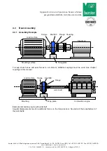
Page 10: ...ermiche e meccaniche 4 3 Basic Assembly 4 3 1 Assembly Example To keep shear forces and axial forces to a minimum shiftable couplings must be used See chapter couplings in this manual Example combusti...

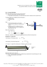
Page 11: ...er bore is suitable for the lead through of hydraulic hoses pneumatic hoses rods Note The lead through part may not acquire torque which will influence the measurement result Applied torque Ms for twi...

Page 12: ...n forces and increases the durability of the couplings and the shaft bearing Frequently an alignment of the couplings with a straight edge in two levels vertical to each other is sufficient At high sp...

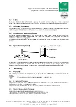
Page 13: ...the measuring signals If troubles occur through the measuring cable we recommend to lay the cable in a grounded steel conduit 5 5 Speed Sensor Option A hall sensor is located between the pulse wheel a...

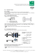
Page 14: ...quency in Hz Moment of Inertia in kg m Torsional Rigidity in Nm rad Further methods for the calculation of natural resonances are corresponding purchasable programs or books e g Holzer Procedure Dubbe...

Page 15: ...rical disturbances Magnetic disturbances EMC electromagnetic disturbances Therefore avoid these disturbance variables by decoupling of vibrations covers etc 7 Maintenance Maintenance schedule Action F...

Page 16: ...t be dismantled professionally Couplings may not be damaged Do not strike sensor housings with tools Do not exert punches on the sensor with a tool Do not apply bending moments on the sensor e g throu...

Page 17: ...ration The sensor data are being checked during this calibration 11 2 DKD Calibration The calibration of the sensor is carried out according to the guidelines of the DKD and or DAkkS The surveillance...

Reviews: