background image

BURR KING MFG. CO., INC

1220 Tamara Lane

Warsaw, MO 65355

www.burrking.com

(660)438-8998 • 800-621-2748

Fax (660)438-8991

B

URR

K

ING

M

ODEL

720 

T

WO

W

HEEL

P

ROBE

G

RINDER

M

ODEL

720 

I

NSTRUCTION

M

ANUAL

M

ANUAL OR

A

IR

T

ENSION

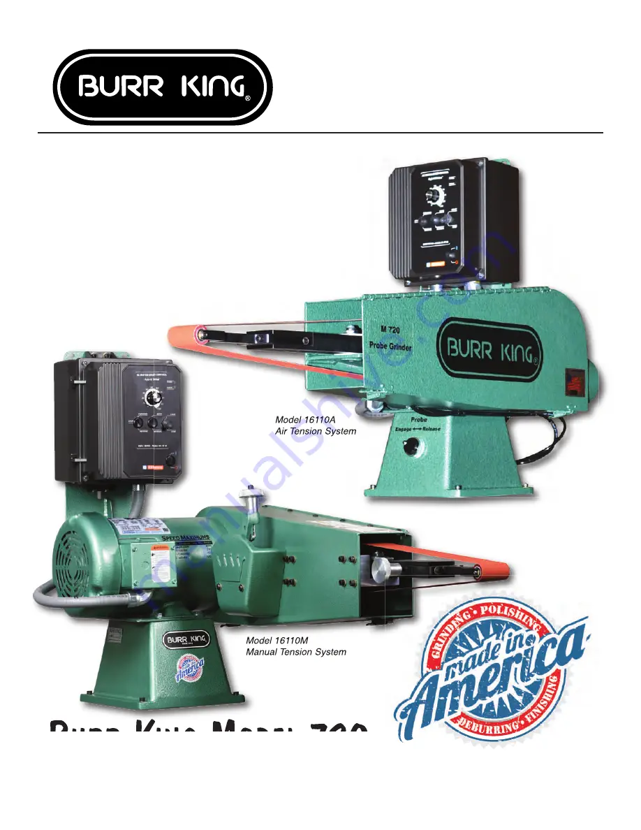
Model 16110A 

Air Tension System

Model 16110M

Manual Tension System

2021 

Design

Summary of Contents for 720

Page 1: ...w MO 65355 www burrking com 660 438 8998 800 621 2748 Fax 660 438 8991 BURR KING MODEL 720 TWO WHEEL PROBE GRINDER MODEL 720 INSTRUCTION MANUAL MANUAL OR AIR TENSION Model 16110A Air Tension System Model 16110M Manual Tension System 2021 Design ...

Page 2: ...ble Burr King Manufacturing Company Inc may elect to make on site service and or repairs necessary to return the product to serviceable condition To assure prompt warranty service it is necessary that you complete and return the below warranty information to Burr King Manufacturing Company Inc please FAX or MAIL at your convenience Product model _______________________ Serial number ______________...

Page 3: ...8 FAX 660 438 8991 October 18 2021 LETTER OF AUTHENTICITY This letter is to certify that all Burr King Belt grinders Disc grinders Polishing machines Vibra King Chambers and Bowls are manufactured and assembled in the United States of America Tariff number 847990 criterion A Don MacCarthy President ...

Page 4: ...L SHOCK Prevent body contact with grounded surfaces For example pipes radiators Disconnect from power source when not in use Never use if electrical cord is damaged or wet Always keep electrical cords clear of rotating parts and belt while in motion Electrical installation shall be in accordance with applicable codes and regulations 5 KEEP CHILDREN AWAY Do Not let visitors contact tool or cord All...

Page 5: ...g when unit is in operation 12 BEFORE SERVICING Disconnect the grinder from the power source 13 NEVER LEAVE TOOL RUNNING UNATTENDED Turn power off Don t leave until the grinder comes to a complete stop 14 DO NOT USE NEAR FLAMMABLE MATERIALS Sparks from the grinder can cause fires 15 HOLD MATERIAL TIGHTLY Always hold the work piece firmly when grinding and apply steady pressure Use work piece holdi...

Page 6: ...NT CAN BE DANGEROUS TO OPERATORS AND THOSE WHO MAY BE IN ITS IMMEDIATE OPERATING VICINITY IT IS THE ABSOLUTE AND DIRECT RESPONSIBILITY OF PURCHASERS MANAGERS AND OPERATORS OF THIS EQUIPMENT TO UNDERSTAND AND OBEY THE FOREGOING MINIMUM OPERATING SAFETY REQUIREMENTS IF YOU HAVE QUESTIONS OR SAFETY CONCERNS REGARDING OPERATING THE SUBJECT EQUIPMENT PLEASE CALL YOUR AUTHORIZED BURR KING DISTRIBUTOR OR...

Page 7: ...as a 4 O D integrated dust collection adapter that will connect to a dust collection system with a recommended minimum capacity of 500 CFPM Use wheels that are the proper size and type for your machine Do not use wheels or belts that are old and or excessively worn Do not operate in a reverse rotation The abrasive belt must rotate CCW when viewed from the right side opposite of the motor Do not ex...

Page 8: ...nd comply with these instructions 7 Ensure that the Model 720 is located in an area that provides safe access to the machine such that operators have clear and unobstructed working space The workplace should be free from floor obstructions trip points and other faults that may reduce operator safety 8 Ensure that the Model 720 AC power source is properly sized for wire and properly fused All wirin...

Page 9: ...ssues cannot be resolved 2 Clean work area and machine Start with a clean area around the machine 3 Check abrasive belt for damage Replace if needed 4 Using the air pressure regulator control located on the incoming air filter assembly adjust the air pressure for air pressure delivery of from 20 50 PSI The greater the air pressure the greater the belt tension 11 Open the guard door RELEASE the pro...

Page 10: ...te smoothly in a CCW direction about the machine wheel belt path as you face the left side of the machine guard door If either of these conditions are not met turn the machine OFF immediately a If the abrasive belt does not remain centered on the contact wheel adjust belt tracking by using the knob on the left side of the probe Adjust this screw either CW or CCW as required to center the belt on t...

Page 11: ...ening wheel life Variable speed motor control allows reduction in drive wheel speed thereby reducing the stress on small diameter wheels For longer nose wheel service life use the following relationships Nose wheel diameter inches Variable speed of maximum 0 5 or less 25 0 6 to 1 0 33 1 1 to 1 5 75 1 6 and larger 100 The Model 720 will accept nose wheels to 4 inches in diameter TIP Pressure Avoid ...

Page 12: ...e machine is running To do so is hazardous Do not use fluids in your grinding process unless your model 720 is designed for liquid operation NEMA 4 4X To do so may create an electrical safety hazard Do not use your model 720 to grind polish explosive materials such unless it is equipped with explosion proof electrical devices and motor Do not mix alloys in your grinding To do so may create an expl...

Page 13: ... 50 52 37 34 31 6 61 5 4 11 42 41 15 10 33 1 46 17 51 53 48 49 30 14 12 21 35 13 20 39 32 9 62 36 29 19 18 29 30 40 8 16 26 27 39 38 44 28 3 22 23 59 47 56 57 54 39 2 24 25 7 43 MODEL 720M EXPLODED VIEW JULY 2020 ...

Page 14: ... 3 30 701F CIRCLIP 5 8 2 31 202B BALL BEARING M10xM30 1 ITEM NO PART NUMBER DESCRIPTION QTY 32 2 0070 S B 3 8 x 2 1 8 1 33 7 0070 SET SCREW 7 16 14 x 7 32 HL 1 34 7 0071 SET SCREW 1 4 28 x 1 3 4 CP 1 35 626 SPRING BELT TENSION 1 36 1 0040 3 8 x 3 8 S B 2 37 720 1 KNOB TRACKING 1 38 707EXM WHEEL IDLER 1 39 25 SET SCREW 5 16 18 X 3 8 CP 3 40 2 0038 SHCS 8 32 x 5 8 5 41 20 NUT NYLOK JAM 1 2 20 1 42 2...

Page 15: ...14 63 14 94 8 05 8 55 3 80 7 25 7 75 31 64 MODEL 720M FOOTPRINT JULY 2020 ...

Page 16: ...16 47 15 28 27 50 11 51 19 22 3 12 20 42 41 2 1 21 17 18 35 39 4 40 26 43 7 25 10 33 23 46 14 45 44 9 38 37 29 30 31 36 8 34 24 5 6 13 32 41 48 49 MODEL 720A EXPLODED VIEW OCTOBER 2020 ...

Page 17: ...IR 1 4 x 1 8 1 23 7221 SPRING TRACKING 1 24 7225 BASE GLIDE 1 25 7229 STUD GLIDE 1 26 7238 BASE CYLINDER 1 ITEM NO PART NUMBER DESCRIPTION QTY 27 4 WASHER 5 16 SAE 4 28 37 CAPSCREW 5 16 18 X 3 4 4 29 5 0023 WASHER FLAT 5 16 USS 4 30 5 0014 WASHER 3 8 INTERNAL STAR 4 31 1 0001 CAPSCEW 3 8 16 x 1 GR 5 4 32 202B BALL BEARING M10xM30 1 33 7 0070 SET SCREW 7 16 14 x 7 32 HL 1 34 7 0071 SET SCREW 1 4 28...

Page 18: ...17 65 14 94 8 05 7 75 7 25 32 77 8 55 3 80 MODEL 720A FOOTPRINT OCTOBER 2020 ...

Page 19: ...wn with 1 x 1 830 Contact Wheel Contact Arm 1423 Shown with 3 8 x 7 16 Contact Wheel Contact Arm 1452 Contact Arm 1443 Contact Arm 1451 Contact Arm 1470 Contact Arm 1490 Wheel Diameters from 3 8 to 3 Wheel Widths from 1 2 to 2 Wheel Hardness from 50 to 90 Duro Wheels Plain Faced Serrated Call Us For Additional Specifications and Options INTERCHANGEABLE ARMS FIT ALL INTERNAL GRINDING ATTACHMENTS Al...

Reviews: