Burley 570-R Series Operating & Installation Instructions Manual Download Page 6


4. 

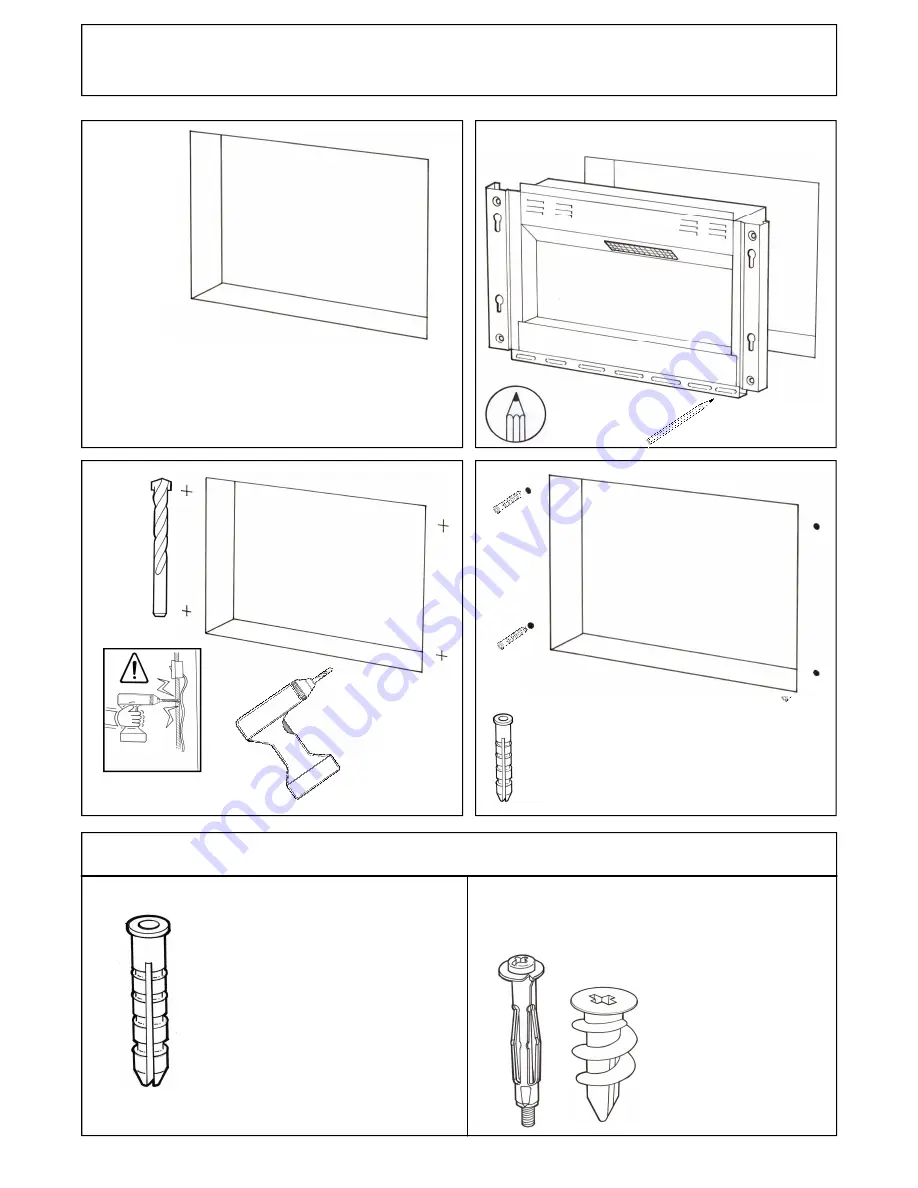
Nylon wall plugs supplied 
suitable for masonry and  
aerated concrete only. 

For plasterboard and cavity wall 
type construction additional 
fixings will be required. 

WALL CAVITY  INSTALLATION INSTRUCTIONS 

6mm 
 

X4 - 570 
X6 - 590 

X4 - 570 
X6 - 590 

Refer to P.3 for cavity sizes 

WALL FIXINGS 

Summary of Contents for 570-R Series

Page 1: ...R Series Burley Appliances Limited Lands End Way Oakham Rutland LE15 6RB U K Telephone 44 0 1572 756956 Fax 44 0 1572 724390 E mail info burley co uk Web www burley co uk CAUTION RISK OF ELECTRIC SHOC...

Page 2: ...is not standing on the cable 7 Before use the appliance must be securely fixed by the method described in the following pages Until it has been fixed in place do not leave it in a location where it co...

Page 3: ...s of the Low Voltage Directive In addition to the safety testing the product has been tested and passed the EMC requirements The product has been tested by TUV SUD in the UK to EN60335 2 30 2009 in co...

Page 4: ...2 PRODUCT CONTENTS X1 X1 Fire 570 or 590 X1 X1 Trim for 570 or 590 X2 X6 570 590 X1 WALL BRACKET X 2 X1 UK EURO X4 X4 570 590 X6 X8 X6...

Page 5: ...S DIMENSIONS Note The sizes allow for clearance at the sides of the fire of 15mm clearance at the top of 20mm and 5mm at the back MODEL 570 590 H W MODEL 570 590 H W D 520 520 686 956 70 70 500 500 65...

Page 6: ...for masonry and aerated concrete only For plasterboard and cavity wall type construction additional fixings will be required WALL CAVITY INSTALLATION INSTRUCTIONS 6mm X4 570 X6 590 X4 570 X6 590 Refer...

Page 7: ...X4 570 X6 590 5...

Page 8: ...im fixings into the four key hole slots and push down the trim to secure Note The trim can be adjusted if required to give a tighter fit on the key hole slots 1 Ensure the nut is finger tight 2 Using...

Page 9: ...7 SURFACE WALL MOUNTED INSTALLATION INSTRUCTIONS 6MM X 4 MIN 570 X 6 MIN 590...

Page 10: ...8 X 4 MIN 570 X 6 MIN 590...

Page 11: ...X 2 POSITIONS LOCKING SCREWS 9 X 2...

Page 12: ...te Refer to P 11 for user instructions Remove the four nuts and spacers from the rear of the trim Fit the four plastic spacers and then nuts to secure the trim Finger tight is sufficient Locate the tr...

Page 13: ...P12 13 P 13 THERMOSTAT USER INSTRUCTIONS 11 Place the optional white chippings onto the glass fuelbed if desired...

Page 14: ...RED TRANSMITTER CONTROL BUTTON REMOTE CONTROL HANDSET 1 PRESS CONTROL BUTTON ONCE FOR THE FLAME EFFECT 2 PRESS A FURTHER TWO TIMES FOR THE FLAME EFFECT AND HEATER 3 PRESS ONCE MORE TO TURN OFF THE FLA...

Page 15: ...eached your desired comfortable temperature c Slowly turn the thermostat down until it clicks and the heater stops d The heater will now cycle on and off to keep the room at the chosen temperature Eac...

Page 16: ...ket it will not get as warm Stop using the socket immediately and call an electrician Many house fires are caused by faulty sockets overheating 6 Flame effect is not working The flame effect movement...

Reviews: