


183
Supplementary information
Type 8792, 8793 REV.2
26
SUPPLEMENTARY INFORMATION
26.1
Selection criteria for continuous valves
The following criteria are crucial for optimum control behavior and to ensure that the required maximum flow
is reached:
•
the correct selection of the flow coefficient which is defined primarily by the orifice of the valve;
•
close coordination between the valve orifice and the pressure conditions in consideration of the remaining
flow resistance in the equipment.
Design guidelines can be given on the basis of the flow coefficient (k
V
value). The k
V
value refers to standardized
conditions regarding pressure, temperature and media properties.
The k
V
value describes the flow rate of water through a component in m³/h at a pressure difference of
∆p = 1 bar and T = 20 °C.
The “k
VS
-value” is additionally used for continuous valves. This indicates the k
V
value when the continuous
valve is fully open.
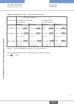
Depending on the specified data, it is necessary to differentiate between the two following cases when selecting
the valve:
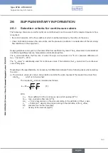
a) The pressure values p1 and p2, known before and after the valve, represent the required maximum flow
rate Q
max
which is to be reached:
The required k
VS
-value is calculated as follows:
(1)
p
p
Q
k
0
0
max
s
v
ρ
ρ
⋅
∆
∆
=
⋅
With:
k
VS
flow coefficient of the continuous valve at full opening [m³/h]
Q
max
max. volumetric flow rate [m³/h]
∆p
0
= 1 bar; pressure loss on the valve according to the definition of the k
V
value
ρ
0
= 1000 kg/m³; density of water (according to the definition of the k
V
value)
∆p pressure loss on the valve [bar]
ρ density of the medium [kg/m³]
english
Summary of Contents for 8792
Page 196: ...www burkert com ...


