Operating Instructions
Bedienungsanleitung Manuel d‘utilisation
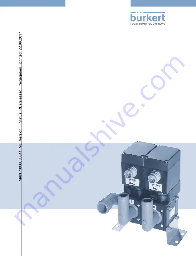
Type 0250
Modular 2 and 3-way motor control valveModulares 2- und 3-Wege-MotorregelventilVanne de régulation motorisée modulaire à 2 et 3 voies
Page 1: ...rating Instructions Bedienungsanleitung Manuel d utilisation Type 0250 Modular 2 and 3 way motor control valve Modulares 2 und 3 Wege Motorregelventil Vanne de r gulation motoris e modulaire 2 et 3 vo...
Page 2: ...ve the right to make technical changes without notice Technische nderungen vorbehalten Sous res rve de modification techniques 2004 2009 B rkert Werke GmbH Co KG Operating Instructions 0910 03_EU ML_0...
Page 3: ...ol functions of the valves 9 Flow characteristic curves 9 Marking 10 Basic module 11 Filter module 11 2 way flow valve 11 3 way mixing or distribution valve 12 Check valve 12 Shut off valve 12 Technic...
Page 4: ...9 Modular filter Type 250 solo 19 Dimensional drawings for modular filter Type 250 solo 19 3 way check valve block with shut off valve 20 Dimensional drawings for 3 way check valve block with shut off...
Page 5: ...the B rkert company Interference with the device is only allowed by specialist personnel using suitable tools Observe the current regulations on accident prevention and safety for electrical devices...
Page 6: ...if the device is used as intended in accordance with the specified application conditions ATTENTION The warranty only extends to the freedom from faults of the motor control valve and its components N...
Page 7: ...rised Transport under the type approval number e1 72 245 2006 96 5806 00 and will be brought into circulation with the indicated approval designation You can obtain an excerpt from the type approval f...
Page 8: ...ired and contains sealing elements from FKM MS and PPS The valve body is made of plastic The electrical rotary actuator with d c motor that is used consists of a maintenance free powerful spur drive w...
Page 9: ...motor driven holds position with no power M P A M P A B M B P A Flow characteristic curves The flow1 characteristic curve for the 2 way valve and the distribution characterisitc for the 3 way valve a...
Page 10: ...l designates the specification key MKEN 0250 or SYST 0250 while the lower cell gives the identity number and the encrypted date of construction Every drive also has its own rating plate with the follo...
Page 11: ...e Description The filter module can be shut off by hand Note the direction of flow As an option the filter module can be fitted with a magnetic insert Block symbol manual lever 4 2 2 way flow valve De...
Page 12: ...tion The 3 way mixing or distribution valve is continuously operated The directions of flow in the distribution valve P A P B in the mixing or distribution valve P1 A P2 A Block symbols Check valve De...
Page 13: ...english 0250 13 english Dimensions Fourfold block Technical data This assembly drawing is an overview of the different constructive possibilities of the motorised control valve...
Page 14: ...2 1 Nm Block assembly with mounting plates and adapters Fixation with fixing angles and tie rods Installation position any preferably with drive above Basic module 2 and 3 way valves Check valve Filt...
Page 15: ...ms Direction of rotation depending on polarity Rotation time for 100 5 approx 7 s at 24 V DC depending on load Electrical connection Round plug according to DIN 43651 6 pole and earth Position feedba...
Page 16: ...on the rating plate of the drive The volta ges and currents must not lie outside the permitted operating range M 1 6 2 4 3 5 P1 Rs Rs 6 8 k P1 1 0 k 5 0 k Plug configuration Note With a pulsed drive a...
Page 17: ...e neutral position Optical position indicator The optical position indicator results from the position of the emergency manual override Turn the emergency manual override the the right outlet port A c...
Page 18: ...ial connection of the modules Operation and function Safety notes Attention Before putting the motorised control valve into operation ensure that the electrical power supply corresponds to the voltage...
Page 19: ...shut off module 191 327 Filter Magnet shut off module 198 066 Dimensional drawings for modular filter Type 250 solo closed open dn 25 p a dn 25 46 40 77 5 113 166 129 65 103 7 35 29 90 adjust ment ra...
Page 20: ...heck valve block with shut off valve Description Order No Check valve block with 192 218 shut off cock Dimensional drawings for 3 way check valve block with shut off valve tu 35 manual lever tu 28 ope...
Page 21: ...orrect operation The manufacturer s data in the technical documentation mechanical and electrical service life Major changes in the system Service intervals Correction of faults If you detect faults t...
Page 22: ...rt in shock resistant packaging Avoid exceeding or dropping below the allowable storage temperature Protect the electrical interfaces of the coil from damage Incorrect storage may damage the device St...
Page 23: ...Funktion 28 Wirkungsweisen des Ventils 29 Durchfluss Kennlinien 29 Kennzeichnung 30 Grundmodule 31 Filtermodul 31 2 Wege Durchlassventil 31 3 Wege Misch oder Verteilerventil 32 R ckschlagventil 32 Abs...
Page 24: ...dularer Filter Typ 250 solo 39 Ma zeichnungen Modularer Filter Typ 250 solo 39 3fach R ckschlagventilblock mit Absperrventil 40 Ma zeichnung 3fach R ckschlagventilblock mit Absperrventil 40 Instandhal...
Page 25: ...satz Installation und Wartungsarbeiten d rfen nur durch Fachpersonal und mit geeig netem Werkzeug erfolgen Beachten Sie die geltenden Unfallverh tungs und Sicherheitsbestim mungen f r elektrische Ger...
Page 26: ...bestimmungsgem e Gebrauch des Ger tes unter Beachtung der spezifizier ten Einsatzbedingungen Achtung Die Gew hrleistung erstreckt sich nur auf die Fehlerfreiheit des Motorregelventils und seiner Baute...
Page 27: ...ter der Typgenehmigungsnummer e1 72 245 2006 96 5806 00 genehmigt und werden mit dem gezeigten Typgenehmigungzeichen in den Verkehr gebracht Einen Auszug der Typgenehmigung erhalten Sie unter der unte...
Page 28: ...us FKM MS und PPS Das Ventilgeh use besteht aus Kunststoff Der eingesetzte elektrische Drehantrieb mit Gleichspannungsmotor besteht aus einem wartungsfreien leistungsstarken Stirnradantrieb mit Magnet...
Page 29: ...orgetrieben stromlos verharrend M P A M P A B M B P A Durchfluss Kennlinien Die Durchfluss1 Kennlinie f r das 2 Wege Ventil und die Verteiler Kennlinie f r das 3 Wege Ventil sind in den folgenden Diag...
Page 30: ...Es bezeichnet in der oberen Zeile den Ger teschl ssel MKEN 0250 oder SYST 0250 in der unteren Zeile die Identnummer sowie das verschl sselte Baudatum Jeder Antrieb verf gt au erdem ber ein eigenes Typ...
Page 31: ...as Filtermodul kann von Hand abgesperrt werden Beachten Sie die Durchfluss richtung Optional kann das Filtermodul mit einem Magneteinsatz ausger stet sein Blocksymbol Handhebel 4 2 2 Wege Durchlassven...
Page 32: ...chreibung Das 3 Wege Misch oder Verteilerventil ist stetigwirkend Die Durchflussrichtungen im Verteilerventil P A P B im Mischventil P1 A P2 A Blocksymbole R ckschlagventil Beschreibung Das R ckschlag...
Page 33: ...0250 33 deutsch Abmessungen 4fach Block TECHNISCHE daten Diese Zusammenstellungszeichnug ist eine bersicht ber die verschiedenen kon struktiven M glichkeiten des Motorregelventils...
Page 34: ...tordrehmoment nom max 1 2 Nm 2 1 Nm Blockaufbau mit Klemmblechen und Zwischenadaptern Befestigung mit Haltewinkeln und Zugstangen Einbaulage beliebig vorzugsweise Antrieb nach oben Grundmodule 2 und 3...
Page 35: ...t erh ht sich die min Pulsdauer ca 100 ms Stellrichtung je nach Polarit t Stellzeit f r 100 5 ca 7 s bei 24 V DC lastabh ngig Elektrischer Anschluss Rundstecker nach DIN 43651 6polig und Masse Stellun...
Page 36: ...s berein stimmen Die Spannungen und Str me d rfen nicht au erhalb des zul ssigen Betriebsbereichs liegen M 1 6 2 4 3 5 P1 Rs Rs 6 8 k P1 1 0 k 5 0 k Steckerbelegung Hinweis Bei getaktetem Antrieb und...
Page 37: ...ellung ein Optische Stellungsanzeige Die optische Stellungsanzeige resultiert aus der Lage der Handnotbet tigung Drehen Sie die Handnotbet tigung nach rechts schlie t sich Ausgang A und Aus gang B wir...
Page 38: ...le Bedienung und Funktion Sicherheitshinweise ACHTUNG Beachten Sie vor der Inbetriebnahme des Motorregelventils dass die Stromversorgungsspannung der auf dem Typenschild ange gebenen Spannung entsprec...
Page 39: ...ell Nr Filter Absperrmodul 191 327 Filter Magnet Absperrmodul 198 066 Ma zeichnungen Modularer Filter Typ 250 solo Zu auf dn 25 p a dn 25 46 40 77 5 113 166 129 65 103 7 35 29 90 stellbereich Zu auf d...
Page 40: ...ach R ckschlagventilblock mit Absperrventil Bezeichnung Bestell Nr R ckschlagblock mit Ab 192 218 sperrhahn Ma zeichnung 3fach R ckschlagventilblock mit Absperrventil tu 35 handhebel tu 28 auF Zu 35 1...
Page 41: ...Herstellerangaben in der technischen Dokumentation mechanische und elektri sche Lebensdauer gr ere Ver nderung im System Wartungsintervalle Beseitigung von Fehlern Haben Sie Fehler festgestellt die si...
Page 42: ...festen Verpackung transportieren Eine ber bzw Unterschreitung der zul ssigen Lagertemperatur vermeiden Elektrische Schnittstellen der Spule vor Besch digungen sch tzen Falsche Lagerung kann Sch den am...
Page 43: ...n de la vanne 49 Courbes caract ristiques de d bit 49 Marquage 50 Modules de base 51 Module filtrant 51 Vanne d admission 2 voies 51 Vanne de m lange ou de r partition 3 voies 52 Clapet antiretour 52...
Page 44: ...ulaire type 250 solo 59 Dessins dimensionnels du filtre modulaire type 250 solo 59 Bloc de 3 clapets antiretour avec robinet d arr t 60 Dessin dimensionnel du bloc de 3 clapets antiretour avec robinet...
Page 45: ...nce ne doivent tre effectu es que par un personnel qualifi quip des outils ad quats Respecter les dispositions en vigueur de pr vention des accidents et de s curit pour appareils lectriques pendant le...
Page 46: ...la construction de machines outils La configuration n cessaire votre applica tion sp ciale sera assembl e par nos collaborateurs du service de visite la client le Utiliser uniquement la vanne de r gul...
Page 47: ...a circu lation automobile Kraftfahrtbundesamt sous le num ro e1 72 245 2006 96 5806 00 et seront mis en circulation avecd la marque d homologation indiqu e Vous recevrez un extrait de l homologation l...
Page 48: ...it en FKM MS et PPS Le bo tier de la vanne est en mati re plastique L entra nement lectrique rotatif utilis par moteur courant continu se compose d un entra nement puissant par pignon droit sans entr...
Page 49: ...restant dans le m me tat sans courant M P A M P A B M B P A Courbes caract ristiques de d bit Les caract ristiques de d bit1 pour la vanne 2 voies et celle de r partition pour la vanne 3 voies sont r...
Page 50: ...e su rieure la cl de l appareil MKEN 0250 ou SYST 0250 sur la ligne inf rieure le num ro d identification de m me que la date de construction cod e Chaque entra nement dispose en outre d une propre pl...
Page 51: ...escription Le module filtrant peut tre bloqu la main Faire attention au sens du d bit Le module filtrant peut tre quip en option d un insert magn tique Symbole fonctionnel Manette 4 2 Vanne d admissio...
Page 52: ...ne de m lange et de r partition 3 voies est action continue Le sens de d bit dans la vanne de r partition P A P B dans la vanne de m lange P1 A P2 A Symboles fonctionnels Clapet antiretour Description...
Page 53: ...n ais 0250 53 fran ais Dimensions Bloc quadruple Caracteristiques techniques Ce dessin d assemblage donne une vue d ensemble des diverses possibilit s de construction de la vanne de r gulation motoris...
Page 54: ...bloc avec t les griffes et adaptateurs interm diaires Fixation par querres de soutien et barres de traction Position de montage quelconque de pr f rence avec l entra nement dirig vers le haut Modules...
Page 55: ...00 ms Sens de r glage suivant la polarit Temps de r glage pour 100 5 env 7 s 24 V DC d pendant de la charge Branchement lectrique Connecteur coaxial selon DIN 43651 6 p les et masse Dispositif de r po...
Page 56: ...l entra nement Les courants et tensions ne doivent pas se trouver hors de la plage d exploitation autoris e M 1 6 2 4 3 5 P1 Rs Rs 6 8 k P1 1 0 k 5 0 k Occupation du connecteur REMARQUE Dans le cas d...
Page 57: ...encliqu te de nouveau en position neutre Affichage de position optique L affichage optique de position r sulte de la situation de la commande de secours manuelle Tournez la commande de secours droite...
Page 58: ...ations dans la jonction des modules Commande et fonctionnement Consignes de s curit ATTENTION Veiller avant de mettre en service la vanne de r gulation mo toris e ce que la tension d alimentation corr...
Page 59: ...le d arr t pour filtre 191 327 Filtre aimant module d arr t 198 066 Dessins dimensionnels du filtre modulaire type 250 solo ferm ouvert dn 25 p a dn 25 46 40 77 5 113 166 129 65 103 7 35 29 90 domaine...
Page 60: ...lapets antiretour avec robinet d arr t D signation N de commande Bloc antiretour avec 192 218 robinet d arr t Dessin dimensionnel du bloc de 3 clapets antiretour avec robinet d arr t tu 35 levier main...
Page 61: ...manipulation des indications du constructeur dans la documentation technique long vit m canique et lectrique modification plus importante du syst me Intervalle d entretien Elimination des d fauts Si...
Page 62: ...un emballage r sistant aux chocs Evitez le d passement vers le haut ou le bas de la temp rature de stockage admissible Prot gez les interfaces lectriques de la bobine des dommages Un mauvais stockage...
Page 63: ......
Page 64: ...www burkert com...