background image


91 


EMAIL TEMPLATES  

Macro email templates allow you to send customized email messages 
containing site and channel data. To create or edit an email template, use 
the 

Tools > Email Templates… 

menu item from the Macro Editor.  


The email template editor always shows all ten templates. To rename a template, select it in the list and then click 
on its label to edit.  

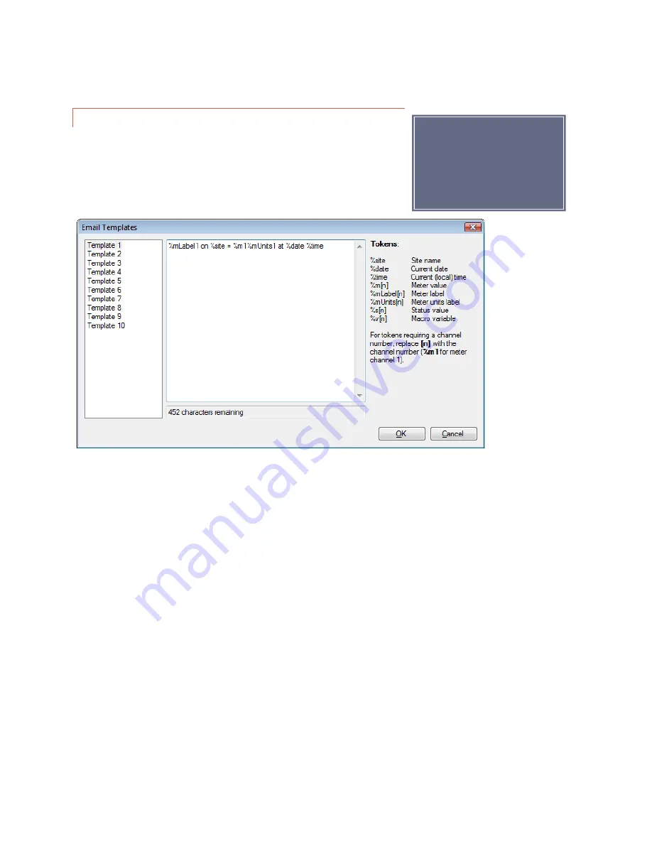
Click on the template name and the text, if any, will appear in the center pane. Use the built-in text editor to enter 
the text for this template. The available tokens are displayed on the right of the screen. Type in the appropriate 
token for the piece of information you wish to include.  All characters that are not part of a token are treated 
literally.  For example, to send an email stating the value of channel 1 and the site name, use the following syntax:  

%mLabel1 on %site = %m1%mUnits1 at %date %time  

Assuming channel 1 is “Forward Pwr”, the email message will be similar to the following: 


Forward Pwr on WXYZ = 2950W at 1/1/2012 9:15:00 AM  

To send an email using a template, use the 

Email Report 

macro command. When that macro command is 

triggered, the ARC Plus will use the selected template to send an email to the list specified in the macro command.  


Note:  

If you’ve used a mail merge 

program, this will be easy.   

Summary of Contents for ARC Plus SL

Page 1: ...1 Instruction Manual ARC Plus firmware version 5 0 Rev D ARC Plus SL ...

Page 2: ... and reliability that will provide years of satisfaction We ve observed that installations go smoothly when the engineer plans the project and allows time for familiarization before jumping in We recommend setting up new units in a comfortable work environment before installing at the transmitter site In addition to hardware familiarization it will also be possible to do much of the configuration ...

Page 3: ...ikely save time later when you need to find a specific piece of information quickly Throughout the manual you will find hypertext links that look like this USING THIS MANUAL Click on the link to go directly to the named section For starters here is a quick set of links to the major sections of the manual USING THIS MANUAL This section ABOUT THE ARC PLUS SYSTEM Information about the models and comp...

Page 4: ...s Model Comparison Model ARC Plus SL ARC Plus1 ARC Plus Touch Version 2 3 5 2 3 4 5 Front Panel Display None VFD Color Touch Screen Rack Height 1RU 2RU 2RU Telephone Speech Option None ESI2 ESI2 RSI3 ESI RSI Connections None SET LINE SET LINE LINE ESI RSI Audio Jacks None 1 1 2 DB9 Serial Connectors None 1 2 24 1 ARC 16 Compatibility AutoPilot Direct5 AutoPilot PlusBus6 Notes The ARC Plus SL is co...

Page 5: ...for example polling up to 500 sites in 5 seconds Warp Engine polling uses very small packets sending only required data and minimizing communications overhead If communications bandwidth is at a premium cost it can be further reduced by selection of a slower polling rate AutoPilot version 2 10 50 or greater must be used for Warp Engine operation NEW IN FIRMWARE VERSION 5 0 2 6 SNMP Plus an optiona...

Page 6: ...ure upload to the ARC Plus SL NEW IN FIRMWARE VERSION 5 ARC Plus Version 5 firmware is the initial release of firmware built for the ARC Plus SL Version 5 hardware This hardware permits increased firmware performance and the addition of new features Version 5 now supports meter and status types that are settable from a macro Commands can now start and stop macros on raise and lower This permits a ...

Page 7: ...ook and new features of the web page SMARTPHONE WEB PAGE Easy to set automatic actions when channels cross limits or change state METER ACTIONS Error Reference source not found Ability to set meter and status values directly from a macro without using a virtual channel METER CHANNEL SOURCE STATUS CHANNEL SOURCE Ability to run two different macros using a single channel s raise lower buttons COMMAN...

Page 8: ...tion 16 Web Page 16 Requirements 16 Security 17 Logging In and Out 17 Navigating the Web Page 17 Smartphone Web Page 20 Installation 21 Needed Items 21 Recommended Sequence 21 Rear Panel Connections 22 Connecting to the Ethernet 22 Initial Settings 22 Network settings 22 Configuration 23 Using AutoLoad Plus Software 23 Connecting to the ARC PLUS SL 23 Saving and Archiving ARC Plus SL Configuration...

Page 9: ...eter Channels 53 Channel and Units Labels 53 Meter Type 54 Voltage Range 54 Sample Type and Time 54 Decimal Places 54 Meter Channel Source 55 Meter Graph 56 Meter Alarms 57 Delayed Alarm Reporting 57 Rearm Delay 57 Enabling Disabling Alarms 58 Setting Limits 58 Meter Actions 59 Meter Notifications 60 Meter Display 61 Meter Speech Labels 62 Calibrating Meter Inputs 63 Status 64 Status Channels 64 I...

Page 10: ...ecking 78 VSWR Computation 78 Macros 79 Macro Primer 79 Branching 79 Actions 79 IF statements 79 Examples 81 Macro expressions 85 General 85 ARC Plus 85 Date and Time 85 Memory 86 Macros 86 Misc 86 Starting and stopping Macros 87 Autopilot 87 WEB Page 87 Raise and Lower buttons 87 Status Actions 88 From a Macro 88 Macro Schedule 88 Configuration 90 Calendar 90 Email Templates 91 Creating Macros 92...

Page 11: ...lus or ARC Plus Touch and automatic coordination of multiple facilities via onboard macros FRONT PANEL ALARM LED The Alarm LED indicates alarm activity By default the LED illuminates red when there is an alarm at the local site It may instead be configured to illuminate when there is an alarm at any site in the ARC Plus network Click or turn to ALARMS for details When no alarm is present the LED i...

Page 12: ...m relay can be used to operate external equipment when an alarm condition exists The relay may be configured to latch closed when there is an alarm at the local site or when there is an alarm at any site in the ARC Plus network A 3 pin connector block is included with the ARC Plus SL FAILSAFE The Form C failsafe relay can be used to interrupt external equipment upon loss of the ARC Plus network li...

Page 13: ...urk com products Facilities Control 1 ARC Plus SL 4 Plus X devices include Plus X Integrated Input Unit Plus X Integrated Command Relay Unit Plus X 300 Plus X 600 Plus X EM Series Environmental Monitors Plus X AC 8 Plus X IP 8 Adapter Plus X GSC Adapter Plus X RP 8 Adapter For specific information on installing and configuring your Plus X accessories refer to the manual for your product Manuals ar...

Page 14: ...f the ARC Plus system including network settings site names channel configuration and network settings With the exception of the initial IP address all ARC Plus SL setup is accomplished via AutoLoad Plus locally or remotely An IP connection is required Click or turn to USING AUTOLOAD PLUS SOFTWARE ...

Page 15: ...the ARC Plus SL in your web browser For more on this feature click or turn to WEB PAGE The web server also provides connectivity to compatible mobile devices To access the mobile web display from your mobile device enter the IP address or host name followed by mobile Click or turn to SMARTPHONE WEB PAGE SOFTWARE AND FIRMWARE UPDATES Periodic updates to ARC Plus software and firmware along with rel...

Page 16: ...utoPilot software described in a separate manual WEB PAGE Before logging into the ARC Plus SL web page follow the steps in NETWORK SETTINGS to change the default IP address from 192 168 0 100 to the address you want to use REQUIREMENTS The ARC Plus SL web page is designed to work well on a PC tablet or smart phone The Web page does not require Java ...

Page 17: ...he Macros page displays a list of the macros on your ARC Plus SL along with their status Use the Run and Stop buttons to run stop a macro ALARMS The Alarm page displays the alarms on this ARC Plus SL with these fields Use the Clear link to clear an alarm or Clear all alarms to clear all Use the Show more or Show all links at the bottom of the page to display more alarms When all alarms are display...

Page 18: ...S The Reset to Factory Defaults link on the web page will reset the ARC Plus SL to its factory default settings except for your network settings and authorization codes The page will show a confirmation Resetting to the Factory Default including the network settings can be done as follows 1 Unplug the unit 2 Press and hold the front panel switch 3 Plug in the unit while holding in the switch 4 Wai...

Page 19: ...k Editor always shows all 16 banks To name a bank first select it and then click on its label in the list and type in a new name Each channel bank can contain any number of meter status and command channels To add channels to a bank 1 Select the channel bank 2 Select the Meter Status or Commands tab 3 Select the channel s you want to add from the left hand list and click the Add button You can add...

Page 20: ...n you log on client side code creates a one way hash of your password to send to the ARC Plus SL NAVIGATING When you log on to the smartphone interface you will see the Channels page This page displays your meter status and command channels in a vertical list If you have more channels than fit on one screen scroll down to see more channels As with the web interface use the Group list to select a c...

Page 21: ...L and peripherals RECOMMENDED SEQUENCE The following sequence assumes the unit is unpacked and powered up at the bench First read the Introduction section of this manual As you read descriptions in the manual it will be useful to follow along on the actual unit Step Reference or Hyperlink 1 Perform the network setup Click or turn to NETWORK SETTINGS 2 3 4 5 6 7 8 9 10 Perform network setup on peri...

Page 22: ...dress NETWORK SETTINGS The ARC Plus SL ships with a default IP address of 192 168 0 100 You will need to connect a PC running AutoLoad Plus software to the ARC Plus SL at this IP address before you can change the network settings on the unit One way to do this is to unplug your PC from any other LAN and connect your PC to the ARC Plus SL via a network switch Then configure your PC with a compatibl...

Page 23: ...s AutoLoad Plus CONNECTING TO THE ARC PLUS SL To modify ARC Plus SL settings using AutoLoad Plus start by launching AutoLoad Plus AutoLoad Plus will prompt for connection settings Enter the IP address and your user name and password for the ARC Plus SL site you are connecting to Then click Connect The default user name is admin and the default password is password The Connect dialog automatically ...

Page 24: ...connect to the desired ARC Plus SL site and click the Open from File toolbar icon Select the desired file click Open and the settings will populate in AutoLoad Plus Press the Save toolbar icon to save the configuration to the ARC Plus SL UPLOADING FIRMWARE Programs Burk Technology AutoLoad Plus 1 Enter the IP address and port normally 2000 of the ARC Plus SL 2 Enter the username and password for a...

Page 25: ...anually or automatically Automatic assignment is recommended in most cases Select the channel number where you want to start assigning channels For your first Plus X device starting at channel 1 is typical Leave the Map the default set of channels checkbox checked and press OK If installing additional Plus X devices assign them to start after the last used channel For example if you are installing...

Page 26: ...er a name and password Once the new user appears on the user list assign privileges by selecting an option from the Level column System Full access to the ARC Plus system This level is required to make configuration changes using AutoLoad Plus Operators Can issue commands run and stop macros clear alarms and calibrate channels Observers Read only access You can rename an existing user by simply ed...

Page 27: ...ynchronize button AutoLoad Plus will set the ARC Plus SL site to the time shown on your Windows clock adjusting for any time zone difference To configure the ARC Plus SL to synchronize with an SNTP time server use the SNTP tab Enter the time server IP address port and rate in minutes at which the ARC Plus SL should synchronize Note Using an SNTP server is recommended to ensure accurate timestamps ...

Page 28: ...Timeouts checkbox If you are unsure of the settings to use contact your network administrator Note In order to reference a mail server by host name instead of IP address a DNS Server is required If your firewall is configured to block access to port 80 the HTTP Port setting can be used to change the port on which the embedded web server communicates If for security reasons you wish to turn off the...

Page 29: ... ARC PLUS SL AS AN SNMP MANAGER This section describes settings that govern the ARC Plus when it acts as an SNMP manager controlling SNMP enabled devices at the transmitter site or other locations SNMP Plus must be enabled on each ARC Plus SL unit by entering an authorization code in the ERROR REFERENCE SOURCE NOT FOUND tab in the site settings dialog box Acting as an SNMP manager the ARC Plus SL ...

Page 30: ...articular device will be identified within the ARC Plus system and can be set to a convenient text string The values for IP Address and UDP Port as well as the Read and Write community strings must agree with the corresponding settings in the SNMP device to be controlled You can configure the rate at which the ARC Plus polls each connected SNMP device from 1 to 255 seconds The default rate of 1 se...

Page 31: ...ections Edit SNMP Devices Show OIDs SNMP MIB BROWSER Each SNMP managed device has one or more associated MIB Management Information Base files MIB files describe each parameter that can be retrieved from a managed device and each parameter that can be configured on a managed device AutoLoad Plus includes a MIB Browser that allows you to import MIB files supplied by equipment manufacturers and to b...

Page 32: ...MIB files Often a manufacturer will supply a directory or zip file containing several MIB files related to a particular piece of equipment To add these files to the AutoLoad Plus MIB Browser click the Add button next to the MIB file list Then browse to and select one of the MIB files supplied by your equipment manufacturer When you select the file AutoLoad Plus will import it into the MIB browser ...

Page 33: ...meter to an ARC Plus meter status or command channel DISPLAY THE CURRENT VALUE OF A MIB PARAMETER The final function of the MIB Browser is to allow retrieval of a test value for the selected MIB parameter Clicking the Get button will cause an SNMP Get command to be sent to the device requesting the current value of the highlighted parameter In the example shown above the retrieved value for ifNumb...

Page 34: ...set to mute while an alarm condition is active SNMP trap generation for that channel will stop If a channel is taken out of mute while an alarm condition is active SNMP trap generation for that channel will begin SENDING PRECONFIGURED TRAPS When the Send traps on alarm box is checked the following four preconfigured ARC Plus Trap Messages are enabled Trap OID Trap meaning 1 3 6 1 4 1 26079 2000 1 ...

Page 35: ...een the user can specify up to 64 custom trap OIDs each one to be triggered by the occurrence of a user selected alarm type on a user specified meter channel or status channel Custom Trap Messages will be sent only if the Enable custom traps box is checked Custom traps are sent using the SNMP v1 message format The custom SNMP traps specified on this page can be sent repetitively during the time th...

Page 36: ...worked with another ARC Plus configured with ESI or using RSI when networked with an ARC Plus Touch configured with RSI Each alarm can be linked to an email notification list and or a dial out list to alert personnel to out of tolerance conditions or system alarms such as an offline ICRU In order for email alarm notifications to be sent the ARC Plus SL must have access to an SMTP server Configurin...

Page 37: ... the mail server and the server port If referencing the mail server by name a DNS must be entered in the Network Settings configuration Click or see NETWORK SETTINGS Emails originating from the ARC Plus SL must have a From address and a Reply address Any undeliverable notifications will be sent to the reply to address Most administrators simply enter their own email address for both of these setti...

Page 38: ...ders including Gmail mail com GMX and Zoho It is suggested that you create an email account dedicated for use with your ARC Plus systems This will make it easier to identify and sort email received from the ARC Plus systems and to monitor email activity To configure the ARC Plus system for use with the cloud service complete the following additional configuration steps 1 Check the Enable Cloud Ema...

Page 39: ...n the selected list Now that you have created at least one email list this list will be available for selection in the Meter Notifications and Status Notifications tabs when you configure ARC Plus SL channels CONFIGURING DIAL OUT ALARM NOTIFICATIONS If an RSI is installed in any ARC Plus in the network metering and status alarms can trigger dial out notifications to telephone numbers on your dial ...

Page 40: ...the Add button plus sign icon to the right of the Phone Numbers column and assign telephone numbers to this list The dial out lists are stored here on the ARC Plus SL and are called out through networked ARC Plus units configured with ESI or RSI Note If you wish for an alarm notification to dial a modem equipped PC running AutoPilot precede the telephone number with D for data This is a useful way...

Page 41: ...ied duration after startup This feature can be used to prevent macros from using readings from equipment that has not yet stabilized or sending commands to equipment that has not yet come back online For older systems installed with legacy PlusBus ICRU units the Restore relay states box allows you to configure the behavior of the ICRU relays upon recovery from a loss of power Check the Restore rel...

Page 42: ...uts After certain connection errors AutoLoad Plus AutoPilot and the ARC Plus SL will log events and or display error messages The Web interface will log off after the specified inactivity period Timeout durations are user configurable in the Timeouts tab ...

Page 43: ...every channel check the box marked Show all status conditions Otherwise the front panel status report will only include status on messages The Front Panel Passcode feature available in firmware version 5 0 1 1 or higher adds enhanced security to your ARC Plus The passcode entered in the field shown above can consist of up to 8 numeric digits After the passcode has been set on the ARC Plus the fron...

Page 44: ...ail notifications of system alarms email server settings and at least one email notification list must be configured Click or turn to CONFIGURING EMAIL ALARM NOTIFICATIONS In order to select a dial out list an RSI must be installed and there must be at least one dial out notification list created Click or turn to CONFIGURING DIAL OUT ALARM NOTIFICATIONS The Alarm on Lost Plus X Device box is check...

Page 45: ...onfigured with ESI or using RSI when networked with an ARC Plus configured with RSI Because more than one RSI or ESI Plus may be installed in a network of ARC Plus systems the ESI tab allows you to configure primary and backup sites Note Depending on how you configure your ARC Plus some activities may generate a high volume of events For example running macros frequently will generate many macro e...

Page 46: ... setting determines how long the ARC Plus SL will wait for a response from the primary RSI or ESI Plus The ESI site max retries setting determines how many times it will retry the primary site before attempting to connect to the Backup ESI site WEB INTERFACE Edit Settings Site Settings Web Interface The Web Interface tab allows you to customize the web interface welcome message MODEM SETTINGS Edit...

Page 47: ...g AutoPilot or SNMP Plus with this ARC Plus SL The Captures feature is automatically enabled and does not require an authorization code for Version 5 ARC Plus Touch and SL units manufactured after January 2017 CAPTURES The Captures feature available on ARC Plus SL units with firmware 5 0 8 1 or newer allows you to configure the ARC Plus SL to store periodic captures snapshots of a specified range ...

Page 48: ...izard See ARC PLUS NETWORK WIZARD in the AutoPilot Guide The Captures feature is automatically enabled without an authorization code on all Version 5 ARC Plus Touch and SL units manufactured in January 2017 or later Edit Setting Site Settings Captures Note Version 5 ARC Plus Touch and SL units manufactured prior to January 2017 require an authorization code to enable the Captures feature If you ha...

Page 49: ...pture times at midnight 1 15AM 2 30AM 3 45AM etc SPECIFYING CAPTURE CHANNELS Captured data always includes Channel 1 and can be set to include up to the entire 256 channels A large block of memory is reserved to store the captured values locally on the ARC Plus SL When this memory fills up the oldest set of captured data is discarded making room for a new capture In this way the most recent captur...

Page 50: ...nels are used you can remove unused channels from display by clicking the Hidden Channels tab and checking off boxes under the Hide heading This will remove the metering status and command channels from view Note If you have a block of channels to hide or unhide choose Hide Unhide Channels from the Tools menu to select channels in blocks ...

Page 51: ...etwork can make it easier to navigate between sites To add a category name choose Add Base Category from the Edit Site List menu and add as many root level categories as desired You can then create subcategories by choosing Add Category from the Edit Site List menu SETTING THE NETWORK PASSWORD Tools Set Network Password Each ARC Plus site has a network password that is used when connecting to othe...

Page 52: ... second at each remote site If communications bandwidth is at a premium cost it can be further reduced by selection of a slower poling rate MACRO PRESETS To set up the preset numbers used to identify macros during an RSI session open the ESI Macro Presets dialog from Edit Settings ESI Macro Presets and select macro names to be associated with as many presets as desired Edit Settings ESI Macro Pres...

Page 53: ...s METER CHANNELS The Meter Channels tab permits entry of the channel label units label sample type decimal place and source CHANNEL AND UNITS LABELS Under the Label and Units Label headings enter names for the metering channel and the unit of measurement These labels appear on the front panel web page and in AutoPilot Each meter channel label can include up to 20 characters Units labels can includ...

Page 54: ... which provides a 10mV degree output The decimal setting for channels configured for degree is locked at 1 000 0 Indirect Multiplies the raw input voltage by the scaled value of the previous channel and multiplies the product by a calibration constant Power Squares the raw input voltage and then multiplies the product by a calibration constant VOLTAGE RANGE The voltage range is always 10 to 10 on ...

Page 55: ... This is the most common selection Virtual Channel Calculates a value for this channel Click or turn to VIRTUAL Channels for instructions Set by a macro Using an SNMP Parameter as a Meter Channel Source This option allows a macro to set this channel s value To assign the value use the Set command in a macro Click or turn to MACRO EXPRESSIONS or in Jet Active Flowcharts in AutoPilot Set by SNMP Thi...

Page 56: ...yed by clicking the Calculate Value button If desired the scale factor used in the calculation can be manually adjusted by changing the value in the Multiply by box In certain cases a manufacturer may specify a MIB parameter with an integer data type when it is actually a floating point number This is to overcome an inherent limitation in the SNMP data formats Usually in these cases the text descr...

Page 57: ...EARM DELAY The ARC Plus has a built in mechanism to reduce multiple alarm reports due to a single alarm event An out of tolerance metering channel that returns to tolerance must remain within normal limits for a period of time before a new alarm is issued on that channel Use the Rearm Delay column to specify this period For example a channel configured to cause a high temperature alarm immediately...

Page 58: ...il alarm reporting and or dial out notifications are enabled dial out requires connection to an ARC Plus equipped with RSI or ESI outbound notifications will also be sent When entering your limits keep in mind the lowest limit value should be the critical low and the highest should be the critical high AutoLoad Plus will automatically adjust limits if they are entered in an order other than least ...

Page 59: ...diately when the limit is crossed In firmware version 5 0 8 1 or later the meter action is executed after the corresponding Alarm Delay as configured on the Meter Alarms tab See DELAYED ALARM REPORTING Meter Actions Tab To configure an action navigate to the Meter Actions tab Hover over the cell and click the button for the channel and limit that you want to set Select the type of action raise low...

Page 60: ...ritical thresholds and warning thresholds can each initiate phone calls and emails to separate lists To set up notification list assignments navigate to the Meter Notifications tab and use the drop down lists to select the email lists and dial out lists each alarm will use Before a list is available for selection it must be created using the Alarm Notifications dialog Click or turn to EMAIL AND DI...

Page 61: ...annels will appear the same on every PC used to access the site Under the Min Value and Max Value headings choose the lower and upper bounds for the meter display in AutoPilot and the web page Then click the icon to modify the color selections for each segment of the meter By default meters show red for the ranges outside of critical limits yellow for the ranges that encompass warning limits and g...

Page 62: ...r Speech Labels tab assign pre recorded vocabulary to each channel and unit label This vocabulary is used when an RSI is reporting conditions via a telephone connection Click the icons to assign RSI vocabulary Additional words or phrases may be added to the RSI vocabulary using the speech editor Consult the documentation for the networked ARC Plus running RSI ...

Page 63: ...meter being monitored The calibration process sets that calibration constant To calibrate a metering channel 1 Choose the channel you want to calibrate by selecting the corresponding row in the Meter Channels tab 2 Click the wrench icon on the far right side of the grid 3 The calibration window will display the current channel scaled value and resolution 4 To change the value of the metering chann...

Page 64: ... status inputs STATUS CHANNELS Under the On Label and Off Label headings enter names for the status on and status off conditions respectively Labels can be up to twenty 20 characters INVERTING A STATUS CHANNEL Normally a status high input results in the ARC Plus showing a status on condition If you want a status low input to result in the on condition check the box under the Invert heading ...

Page 65: ...use the Set command in a macro Click or turn to MACRO EXPRESSIONS or in Jet Active Flowcharts in AutoPilot Set by SNMP This option instructs the ARC Plus to populate the status channel based on data retrieved from an SNMP enabled device See USING AN SNMP PARAMETER AS A STATUS CHANNEL SOURCE USING AN SNMP PARAMETER AS A STATUS CHANNEL SOURCE Set by SNMP has been selected in the Source dialog shown ...

Page 66: ...Value should be selected In this case the value corresponding to the ON condition for this parameter should be entered in the corresponding box STATUS ALARMS Set up alarm characteristics for each status channel on the Status Alarms tab ENABLING DISABLING ALARMS To configure status alarms select the desired alarm behavior under the Alarm Behavior heading A status channel can cause an alarm when the...

Page 67: ...o a single alarm event A status channel in alarm must remain in its normal state for a period of time before a new alarm is issued on that channel Use the Rearm Delay column to specify this period ALARM SEVERITY Status alarms may be configured as warning alarms or critical alarms Both types of alarms are reported in the same ways front panel email notifications dial out behavior etc The designatio...

Page 68: ...xecuted immediately when the status changes state In firmware 5 0 8 1 or later the status action is executed after the corresponding Alarm Delay as configured on the Status Alarms tab See DELAYED ALARM REPORTING To configure an action navigate to the Status Actions tab and click the button in the appropriate field for the channel and state that you want to set Select the type of action raise lower...

Page 69: ...of status alarms Before a list is available for selection it must be created using the Alarm Notifications dialog Click or turn to CONFIGURING DIAL OUT ALARM NOTIFICATIONS STATUS DISPLAY AutoPilot software and the web page both show on and off indicators for the status channels To change which colors are used navigate to the Status Display tab and click the icon next to each status on or status of...

Page 70: ...ured as either momentary or latching Make this selection under the Command Type heading Momentary relays are energized for the duration configured under the Command Duration heading Latching channels are energized until the opposing relay is activated i e when a channel is latched in the raise state the raise relay is energized until the lower relay is activated COMMAND DURATION The command durati...

Page 71: ...e The raise and lower buttons provide 24 characters for the command label 3 lines of 8 characters each In AutoLoad Plus hover inside the Raise label or Lower label field and then click next to the label text to open the Command Label dialog box Enter the channel label and click OK ...

Page 72: ...t Indicates that a command channel is not in use PlusBus Not used in version 5 Plus X This option allows you to map a Plus X channel This is the most common selection Macro This option allows you to run a macro by issuing a raise or lower command to the channel Two different macros may be assigned to a channel s respective raise and lower commands Note You can always run stop macros from the macro...

Page 73: ...to ensure that the Raise and Lower functions are not active at the same time 2 The delay specified in the Command Duration setting is observed before executing step 3 3 The command is completed by transmission of the specified Raise Off OID The Lower Off OID is also sent at this time For Lower commands on channels set to Momentary 1 A Lower command causes transmission of an SNMP OID as specified i...

Page 74: ...it is only necessary to program the Lower On OID value In this way the latching function for SNMP devices is analogous to the operation of latching relays See MOMENTARY OR LATCHING RELAYS Clicking on the Browse button in the SNMP Command Binder invokes the SNMP MIB BROWSER to identify the desired SNMP parameter OID for the raise or lower function The Command Binder also lets you specify the data t...

Page 75: ...expression field that channel would always read 100 Typing 50 50 would do the same thing The terms and operators in the expressions can be any of the types listed on the source page M1 for instance represents the current value of the first meter channel You could if you like display the sum of meter 1 and meter 2 on another channel by this expression If Meter 1 is ambient temperature and Meter 2 i...

Page 76: ...is on MIN MAX AVERAGE The ARC Plus SL allows for setting metering channels to normal minimum maximum or average Typically the real time value is also to be displayed so put any desired calculated values on virtual channels In fact you could devote 4 channels to one input using separate virtual channels for min max and average One channel would be the actual input say Meter 1 and the other three wo...

Page 77: ...nd do the same thing but alarms on efficiency work just as well STATUS BASED ON ANALOG LIMITS You can also set a channel based on analog limits While you would normally alarm on limits there may be situations where you would prefer to log values as a status rather than an alarm Here is an example assuming Meter 1 is Power Out A status channel is set to be virtual and the following expression is en...

Page 78: ...g that it is actually on XOR is the exclusive OR operator meaning that either one or the other condition is true but not both The truth table looks like this R1 S1 Result Condition 0 0 OK TX off 0 1 Fault TX on with no command 1 0 Fault TX command on but no response 1 1 OK TX on If no status signal is available there may be a metering value you can use like this R1 XOR M1 90 To prevent false alarm...

Page 79: ...To perform a loop put a goto on the line following the steps to be looped followed by the line number of the first action If there are no if statements branching out of the loop it is an infinite loop If the action needs to end when a value is reached include an If statement in the loop which includes a goto to a line outside the loop such as an end statement at the end of the program ACTIONS Acti...

Page 80: ... statement The comparison we are evaluating is a status input being compared to a literal value The status input is labeled LOAD OFF LOAD ON and the literal we are comparing with is LOAD ON If the expression evaluates to true we are branching to line 4 In plain English If the load is on then skip to line 4 else continue on line 2 Line 2 doesn t get executed unless the branch from line 1 is not tak...

Page 81: ... maintenance day Check out MACRO SCHEDULE to see how to set the time 1 If day Tuesday goto line 3 2 Raise Start Coffee on site BURK FM for default 3 End macro MUTE METERS In this example all we want to do is grey out the meters on the A transmitter This macro could be called from another macro that put the B transmitter on the air You would also need unmute macros for each transmitter 1 Set meter ...

Page 82: ...oto line 1 2 Send email message more than 10 alarms to email list Chief 3 Wait for 01 00 00 4 Goto line 1 TRANSMITTER START SEQUENCE Here is a tube transmitter startup that skips the filament turn on and delay if filaments are already on 1 If status of TX A FIL ON TX A TX A FIL OFF on site BURK FM TX A FIL ON goto line 4 2 Raise TX A FIL ON on site BURK FM for default 3 Wait for 00 05 00 4 Raise T...

Page 83: ...TX A ON ANTENNA on site BURK FM TX B ON ANTENNA goto line 9 3 Message ATTEMPT XFER TO B 4 If status of TX B FAULT TX B OK on site BURK FM TX B FAULT goto line 13 5 Lower TX B TO AIR on site BURK FM for default 6 Wait for 00 00 01 7 Turn macro AUTO ON on 8 End macro 9 Message ATTEMPT XFER TO A 10 If status of TX A FAULT TX A OK on site BURK FM TX A FAULT goto line 13 11 Raise TX A TO AIR on site BU...

Page 84: ...bes are set up as latches The schedule for this macro is set for interval 1 Raise TWR1 ON on site BURK FM for default 2 Wait for 00 00 05 3 Set 1 Phase on BURK FM MON PHASE on BURK FM 4 Set 1 Ratio on BURK FM MON RATIO on BURK FM 5 Lower TWR1 OFF on site BURK FM for default 6 Raise TWR2 ON on site BURK FM for default 7 Wait for 00 00 05 8 Set 2 Phase on BURK FM MON PHASE on BURK FM 9 Set 2 Ratio o...

Page 85: ...ction to test the result of a raise lower command If Relay State Tests if the state of a relay is latched or unlatched If Alarm Tests the expression against the alarm count at the specified site Can be used with an inequality to trigger an action if the alarm count is greater than 0 If Maint Mode Tests the expression against the maintenance mode on off state at the specified site Raise Lower Issue...

Page 86: ...ff A macro that is scheduled to run but is not currently executing instructions is considered to be stopped Set Macro Runs or stops the specified macro MISC Wait Programs the macro to pause for the specified duration before executing the next line of code Message Generates a new entry in the ARC Plus event log with the specified message text Note that messages do not initiate any email notificatio...

Page 87: ... name WEB PAGE From the web page of the ARC Plus SL select the Macros tab All macros are available here and can be started and stopped by pressing the Run or Stop buttons RAISE AND LOWER BUTTONS Using AutoLoad raise and or lower buttons on any channel can be assigned to a macro start or stop command On the AutoPilot commands tab hover over the source cell for the desired channel and click on the b...

Page 88: ...e desired macro in the Action target field FROM A MACRO A macro that is running can include an instruction to start or stop another macro This is useful for chaining complicated sequences and for reusing common sequences in different scenarios MACRO SCHEDULE The following start stop methods can be set from the Macro Schedule dialog box On the macro editor click on the cell next to Schedule in the ...

Page 89: ...AL A macro can be scheduled to run at a scheduled interval such as every 15 seconds or once an hour Click the Run at an interval radio button and specify the number and units seconds minutes or hours TIME To run at a specific time every day choose the Schedule for a specific time radio button and enter the time CALENDAR TIME This function allows a set of calendars in the ARC Plus SL which are cust...

Page 90: ...d User 2 Set up the schedule by clicking under the appropriate heading and using the arrows to set the desired time When a macro references one of these presets times it will use the time of day configured here Use standard time when programming the calendar the ARC Plus will automatically adjust for Daylight Saving Time if configured to do so Click or turn to TIME SETTINGS Note Calendars are labe...

Page 91: ...played on the right of the screen Type in the appropriate token for the piece of information you wish to include All characters that are not part of a token are treated literally For example to send an email stating the value of channel 1 and the site name use the following syntax mLabel1 on site m1 mUnits1 at date time Assuming channel 1 is Forward Pwr the email message will be similar to the fol...

Page 92: ... Plus by selecting Macros from the Edit Settings menu This opens the Macro Editor 2 Select an empty macro from the navigation pane on the left 3 Click on the first line in the editor to select it for editing A dropdown box will appear right below the editor pane 4 Click on the arrow in the drop down box to see a list of commands 5 Select the command for this line 6 Make additional selections to co...

Page 93: ...els By default these labels are Run Macro and Stop Macro If desired you can change these labels by entering text in the Run Label and Stop Label fields in the macro properties list SPEECH LABEL The ARC Plus SL can store speech labels that are called out by a networked ARC Plus configured with RSI In order for an RSI speech interface to report the name of the macro a label must be assigned in the S...

Page 94: ...12 48 26 cm x 8 89 cm x 30 48cm Memory Nonvolatile FLASH memory and battery backed real time clock store data for 20 years without power Front Panel Interface Maintenance Pushbutton Two color alarm LED remote LED Communication Ports RJ 45 Ethernet port for 10 100BaseT network connection DB9 RS 232 port for optional serial or dial up modem connection ...

Reviews: