background image

S3-915M

User manual

3

1. Overview

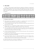
S3-915M is a standard LoraWan node Module designed and manufactured by BuildingLink, working frequency

band 902-928MMHZ, supports CLASS-A/CLASS-C node type, supports ABP/OTAA two network access modes, and at
the same time, this module With a variety of low-power modes, the external communication interface uses a standard
UART. Users can easily access the standard LoraWan network through AT commands, making it an excellent choice for
IoT applications.

1.1 main parameter

Product

model

Core IC

Size

Net weight

working

temperature

Working
humidity

Storage

temperature

S3-915M

ASR6501

20* 14*2.8 mm

1.3±0.1g

-40 ~ 85℃

10% ~ 90%

-40 ~ 125°C

1.2 Parameter Description

When designing the power supply circuit for the module, it is recommended to reserve more than 30% of the
remaining amount, and the whole machine is conducive to long-term stable operation

The current required for the instant of launch is large but often because the launch time is extremely short, the total

energy consumed may be smaller

When the customer uses an external antenna, the impedance matching degree between the antenna and the module
at different frequency points will affect the magnitude of the emission current to varying degrees;

The current consumed by the RF chip in the pure receiving state is called the receiving current. Some RF chips

with communication protocols or developers have loaded some self-developed protocols on the whole machine,
which may cause the receiving current of the test to be too large

The current in the purely receiving state is often mA level, and the "receiving current" of the μA level needs to be
processed by the developer through software;

The shutdown current is often much smaller than the current consumed by the power supply part of the whole
machine at no load, without being overly demanding;

Since the material itself has a certain error, a single LRC component has an error of ±0.1%. However, since a
plurality of LRC components are used in the entire RF loop, there is a case where error accumulation occurs,
resulting in a difference in emission current and reception current of different modules;

Reducing the transmit power can reduce power consumption to some extent, but reducing the transmit power

emissions for a number of reasons reduces the efficiency of the internal PA.

Summary of Contents for S3-915M

Page 1: ...S3 915M User manual 1 S3 915M User Manual LoraWan Module...

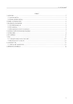
Page 2: ...NICAL PROPERTIES 5 3 1 S3 915M DIMENSIONS 5 3 2 PIN DEFINITION 5 3 3 RECOMMENDED CONNECTION DIAGRAM 6 4 LORAWAN APPLICATION MODEL DIAGRAM 7 5 ACCESS DEMO 8 6 AT COMMAND 10 7 FAQ 27 7 1 COMMUNICATION R...

Page 3: ...antenna the impedance matching degree between the antenna and the module at different frequency points will affect the magnitude of the emission current to varying degrees The current consumed by the...

Page 4: ...ream transmission of the server at any other time has to wait for the next uplink of the terminal Two way transmission terminal delineating a reception slot Class B Class B terminals have more receive...

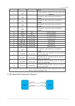
Page 5: ...r supply range 2 5 3 7v external ceramic filter capacitor is recommended 3 SETB Low power wake up pin 4 DIO1 Input output NC reserved pin 5 BUSY Input output NC reserved pin 6 I2C_SDA Input output NC...

Page 6: ..._TX Input output UART TX pin 22 SWD_DATA Input output SWD Data pin 23 SWD_CLK Input output SWD Clock pin 24 GND Ground wire connected to the power reference ground 25 SPI_MISO Input output SPI MISO te...

Page 7: ...ation server the node is generally designed by LORA chip the gateway is designed by SX1301 provided by semtech Lora NetWork Server now has open source loraserver or commercial TTN The ThingsNetwork us...

Page 8: ...3 915M as a node E890 as a gateway to access the free TTN TheThingsNetwork test server for communication test node side OTAA access mode corresponding settings are as follows On the TTN the gateway da...

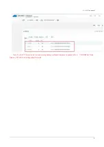
Page 9: ...S3 915M User manual 9 Note For the TTN creation device and corresponding configuration process please refer to LORAWAN Node Gateway TTN Server Configuration Tutorial...

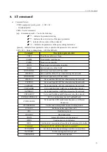
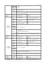
Page 10: ...read join mode OTAA ABP CDEVEUI Set to read DevEUI OTAA when entering the network CAPPEUI Set to read AppEUI OTAA when entering the network CAPPKEY Set to read AppKey OTAA when entering the network CD...

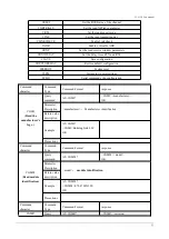
Page 11: ...al command echo configuration Command character Command Type Command Format response CGMI Read the manufacturer s logo Query command AT CGMI CGMI manufacturer OK Parameter Description manufacturer Man...

Page 12: ...e description Example AT CGSN CGSN 0539349E00032523 OK Precautions Command character Command Type Command Format response CGBR Set baud rate Query command AT CGBR CGBR baud OK Setting command AT CGBR...

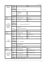
Page 13: ...urn value description Example AT CDEVEUI CDEVEUI AABBCCDD00112233 OK Precautions Set or read DevEUI return Y1Y2 Y8 hexadecimal format and take 8 bytes Command character Command Type Command Format res...

Page 14: ...dr length is 8 Device address of ABP mode Query command AT CDEVADDR CDEVADDR value OK Setting command AT CDEVADDR value OK Parameter Description value Node DevAddr Return value description Example AT...

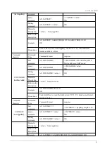
Page 15: ...nd Type Command Format response Test command AT CFREQBANDMASK CFREQBANDMASK mask OK Query command AT CFREQBANDMASK CFREQBANDMASK mask OK Setting command AT CFREQBANDMASK m ask OK Parameter Description...

Page 16: ...value description Example AT CWORKMODE 2 OK Precautions It needs to be set before joining and the default is normal working mode Currently only normal operation mode is supported Command character Com...

Page 17: ...nd AT CJOIN CJOIN ParaTag1 ParaTag2 Para Tag4 OK Query command AT CJOIN CJOIN ParaValue1 ParaValue2 Para Value4 OK Setting command AT CJOIN ParaValue1 ParaValue2 ParaValue4 If the input is legal first...

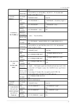
Page 18: ...SENT TX_CNT Parameter Description Confirm and nbtrials refer to the corresponding AT command which is valid only for this transmission optional Length indicates the number of strings the maximum valu...

Page 19: ...NT indicates that the data transmission failed the maximum number of transmissions has been reached TX_CNT 1 Byte and the number of data transmissions OK RECV TYPE PORT LEN DATA Successful data recept...

Page 20: ...IRM value OK Query command AT CCONFIRM DRX Length Payload OK Setting command AT CCONFIRM value OK Parameter Description value as follows 0 UnConfirmed up message 1 Confirmed up message Return value de...

Page 21: ...125 Return value description Example AT CDATARATE 1 OK Precautions Need to be set before sending data invalid after ADR is enabled Command character Command Type Command Format response CRSSI Query ch...

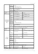
Page 22: ...character Command Type Command Format response CRM Set reporting mode Test command AT CRM CRM reportMode reportInterval OK Query command AT CRM CTXP reportMode reportInterval OK Setting command AT CT...

Page 23: ...haracter Command Type Command Format response CLINKCHECK Verify network connectivity Test command AT CLINKCHECK CLINKCHECK value OK Setting command AT CLINKCHECK value OK Parameter Description value E...

Page 24: ...meter Description AT CRXP RX1DRoffest RX2DataRate RX2Frequen cy OK Return value description RX1DRoffest RX2DataRate RX2Frequency LoRaWAN Example Precautions AT CRXP 1 1 471000000 OK Test command Need...

Page 25: ...ameters for network initialization and operation Precautions Need to save before sending data Command character Command Type Command Format response CRESTOREMAC Restore MAC default parameters Test com...

Page 26: ...ering low power consumption send the serial port command again to wake up Because the UART start part byte may be transmitted incorrectly when transmitting above 40kbps AT CLPM 0 may be recognized as...

Page 27: ...wer Due to antenna quality or poor matching between antenna and module 7 2 Module is easy to damage Please check the power supply source ensure it is 2 0V 3 6V voltage higher than 3 6V will damage the...

Page 28: ...armful interference and 2 this device must accept any interference received including interference that may cause undesired operation FCC RF Radiation Exposure Statement 1 This Transmitter must not be...

Reviews: