background image

TC-Double (+)

2 Safety instructions

2.1 Important advice

Operation of the device is only valid if:

– the product is used under the conditions described in the installation- and operation instruction, the intended application

according to the type plate and the intended use. In case of unauthorized modifications done by the user Bühler Technolo-
gies GmbH can not be held responsible for any damage,

– when complying with the specifications and markings on the nameplates.

– the performance limits given in the datasheets and in the installation- and operation instruction are obeyed,

– monitoring devices and safety devices are installed properly,

– service and repair is carried out by Bühler Technologies GmbH,

– only original spare parts are used.

This manual is part of the equipment. The manufacturer keeps the right to modify specifications without advanced notice. Keep
this manual for later use.

Signal words for warnings

DANGER

Signal word for an imminent danger with high risk, resulting in severe injuries or death if not avoided.

WARNING

Signal word for a hazardous situation with medium risk, possibly resulting in severe injuries or death if not
avoided.

CAUTION

Signal word for a hazardous situation with low risk, resulting in damaged to the device or the property or
minor or medium injuries if not avoided.

NOTICE

Signal word for important information to the product.
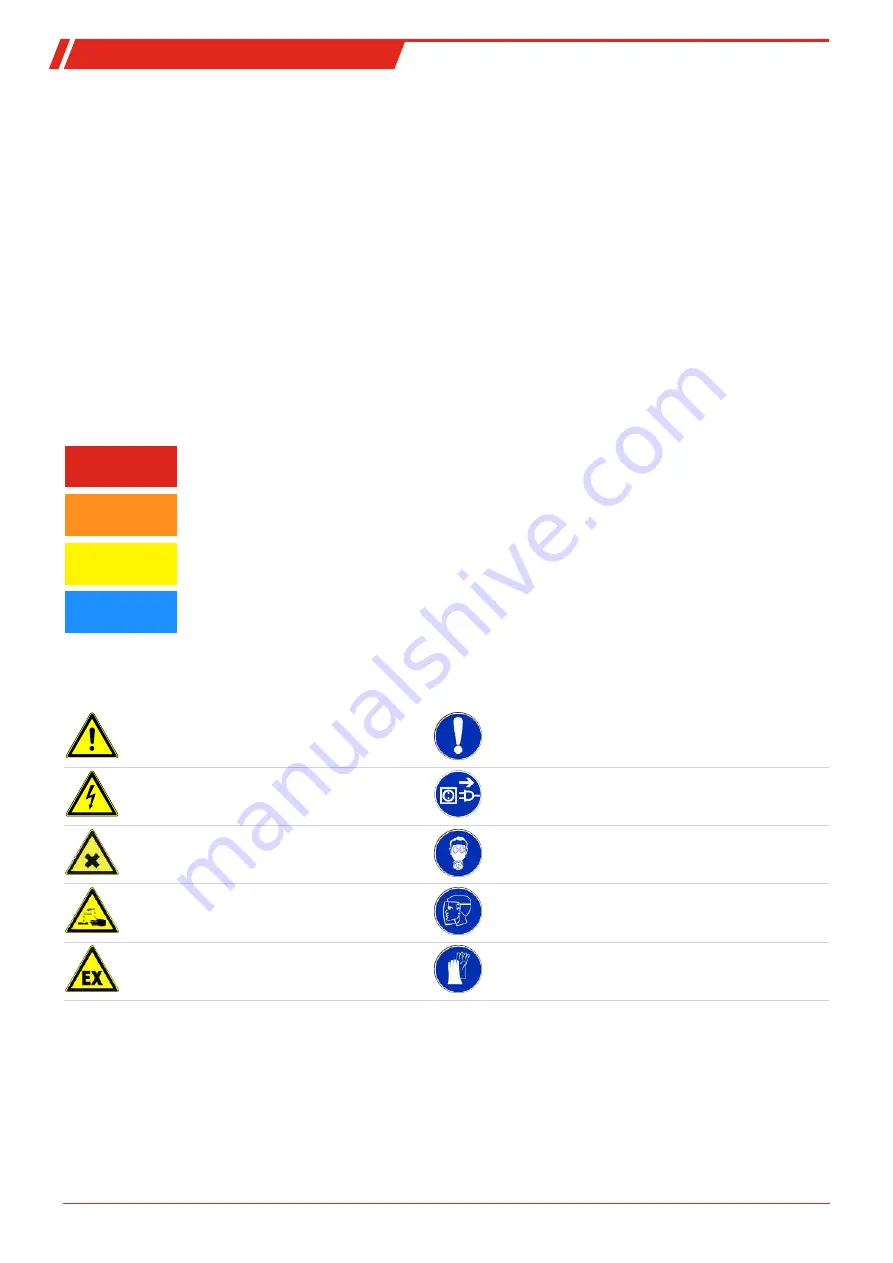
Warning signs

These instructions use the following warning signs:

Warns of a general hazard

General information

Warns of voltage

Unplug from mains

Warns not to inhale toxic gasses

Wear respiratory equipment

Warns of corrosive liquids

Wear a safety mask

Warns of explosive areas

Wear gloves

6

Bühler Technologies GmbH

BE440021 ◦ 09/2021

Summary of Contents for TC-Double Plus

Page 1: ...ns Original instructions Sample gas cooler TC Double BE440021 09 2021 B hler Technologies GmbH Harkortstr 29 D 40880 Ratingen Tel 49 0 21 02 49 89 0 Fax 49 0 21 02 49 89 20 E Mail analyse buehler tech...

Page 2: ...this instruction carefully prior to installation and or use Pay at tention particularly to all advises and safety instructions to prevent in juries B hler Technologies can not be held responsible for...

Page 3: ...cription of menu functions 18 5 3 1 Display menu 18 5 3 2 Main menu 18 5 3 3 Submenu 1 19 5 3 4 Submenu 1 Global Settings 20 5 3 5 Set favourite menu 24 5 4 Using the Digital Interface 24 5 5 Modbus C...

Page 4: ...9 9 2 Technical Data Options 40 9 3 Flow chart 41 9 4 Performance curves 41 9 5 Heat exchanger 42 9 5 1 Heat exchanger description 42 9 5 2 Heat exchanger overview 42 9 6 Dimensions mm 43 10 Attached...

Page 5: ...This classification is re flected in the type designation The exact item number of the model defined by you is determined by the model code in the cat egory ordering information Application Standard a...

Page 6: ...ondensate drain 1 0 without condensate drain 2 CPdouble with hose nipple angled 4 CPdouble with screw connection 2 Sample gas pumps 1 3 0 without sample gas pump 1 P1 PVDF 2 P1 with bypass valve Moist...

Page 7: ...ain 2 CPdouble with hose nipple angled 4 CPdouble with screw connection 2 Sample gas pumps 1 3 0 without sample gas pump 1 P1 PVDF 2 P1 with bypass valve Moisture detector filter 1 2 0 0 without filte...

Page 8: ...art of the equipment The manufacturer keeps the right to modify specifications without advanced notice Keep this manual for later use Signal words for warnings DANGER Signal word for an imminent dange...

Page 9: ...tructions Always use genuine spare parts Do not install damaged or defective spare part If necessary visually inspect prior to installation to determine any obvious damage to the spare parts Always ob...

Page 10: ...e the original packaging or a suitable alternative The equipment must be protected from moisture and heat when not in use It must be stored in a covered dry and dust free room at a temperature of 20 C...

Page 11: ...ltic pumps Connecting the condensate drains Depending on the material build a connecting line with fittings and tubing or hose between the heat exchanger and condens ate drain For stainless steel the...

Page 12: ...outlet at the mounting ring Be sure the gas line connections are tight 4 2 5 Connecting the heat exchanger To minimise gas wash out in the cooler the two identical heat exchangers must be operated in...

Page 13: ...ong mains voltage Wrong mains voltage may damage the device Regard the correct mains voltage as given on the type plate WARNING High voltage Damage to the device in case of insulation testing Do not p...

Page 14: ...ine cross sections must be suitable for the rated current Use a maximum line cross section of 1 5 mm AWG 16 and a cable diameter of 8 10 mm 0 31 0 39 inch Shielded signal lines are required to connect...

Page 15: ...500 Signalling of actual temper ature in block 1 Tcooler 20 C 4 F 4 mA 2V Tcooler 5 C 41 F 9 mA 4 5 V Tcooler 60 C 140 F 20 mA 10 V Regard ing S4 Digital output Modbus RTU RS 485 Interface default val...

Page 16: ...low and excess temperature These are set relative to the outlet dew point a setting For the low temperature the range is a 1 to 3 K at a minimum 1 C 34 F cooling block temperature for the excess tempe...

Page 17: ...isplay if option installed Menu Next Enter Reduce value or browse selection ESC Menu Move one level up Enter Return to menu Changes will not be saved F or Func Sets a menu to favourite Note The favour...

Page 18: ...ill only appear with the respective settings or with the respective status messages The factory defaults and settings ranges are specified in the overview as well as under the respective menu item The...

Page 19: ...Drop down menu PuMP nop off OK Drop down menu h2o Drop down menu sen Moisture detector 1 sensitivity Calibrate moisture detector 1 Confirm rst OK Input non non hi Lo OK yes no Error Err Status message...

Page 20: ...the runtime press the Enter key yy mm display in years and months default mth display in months weeh display in weeks days display in days One month corresponds to 30 days Press the F key to switch be...

Page 21: ...ature Display Cooler temp This setting determines the nominal temperature for the cooler temperature Parameter range 2 C to 20 C 35 6 F to 68 F Factory setting 5 C 41 F Note If the temperature is chan...

Page 22: ...or analog output 1 see chapter Submenu 2 Analog Output 1 Note This menu will be hidden if the menu is locked Calibrate moisture detector Display toP h2o h2o If a moisture detector is installed calibra...

Page 23: ...mps will be deactivated no The error message will disappear The pumps will be switched on again once the moisture de tector is reactivated again Factory setting YES Note This menu will be hidden if th...

Page 24: ...face are not affected when resetting the device to its factory settings This menu item is only available on devices with Digital output Modbus RTU option Display toP addr Defines the ID Parameter rang...

Page 25: ...ent output 4 20 mA Voltage output 2 10 V hi 20 mA 10 V Mi 12 mA 6 V Lo 4 mA 2 V noP 4 20 mA 2 10 V After testing the signal behaviour must be changed back to normal mode noP Display toP An1 cout This...

Page 26: ...bits 1 parity bits configurable 1 stop bit Baudrate 19200 bps configurable Device ID 10 configurable The length of a Modbus frame is always 11 bit configuring the interface at 0 data bits automatical...

Page 27: ...reached Bit 20 Bit 21 31 Not used Block temperature setpoint 3 16 5000 R W Float 5 0 3 0 20 0 0 5 C Positive alarm tolerance setpoint 3 16 5002 R W Float 3 0 1 0 7 0 1 0 K Negative alarm tolerance set...

Page 28: ...6 206 32768 32767 1 TEST_UINT32 3 16 9994 R W Uint32 2766 0 4294967 295 1 TEST_INT32 3 16 9996 R W Int32 2766 0x80000000 0x7fffffff 1 TEST_Float 3 16 9998 R W Float 10 5 Status register overview 3 100...

Page 29: ...rd 2 communication error Bit 3 Controller configuration error Bit 4 EEPROM regulator error Bit 5 Fan error Bit 6 Bit 7 Gen software error Error register 2 3 10006 R Uint16 0 Error register 3 moisture...

Page 30: ...on controller 2 3 R Unit16 0 100 10 Device run time 3 10100 R Float 0 6 min h Restart reset device 16 11000 W Unit16 0x00 86 Restart device 17 Factory reset Reset moisture detector 1 16 11002 W Uint16...

Page 31: ...nal page 35 During maintenance remember The equipment must be maintained by a professional familiar with the safety requirements and risks Only perform maintenance work described in these operating an...

Page 32: ...mail service buehler technologies com 7 1 Troubleshooting Problem Malfunction Possible cause Action Condensate inside the gas output Condensate trap full Empty condensate trap Valve inside the automa...

Page 33: ...nnect from power for approx 5 s Contact service Error 03 Microcontroller fault MCP2 Contact service Error 04 EEPROM error Contact service Fan malfunction fan out of order Check fan blocked Check conne...

Page 34: ...in this manual Only use original spare parts DANGER Electrical voltage Electrocution hazard a Disconnect the device from power supply b Make sure that the equipment cannot be reconnected to mains unin...

Page 35: ...ry disconnect moisture detector from filter or adapter Loosen the fixing bolts for the hood Carefully remove the hood The hood has parts which protrude inward and could cause damage The display module...

Page 36: ...g of the moisture detector option The moisture detector must be dried if moisture enters Close the gas supply Switch off and unplug the device Loosen the swivel nut for the moisture detector connectio...

Page 37: ...lves are further marked IN or for inlet and OUT for outlet Inlet valve Outlet valve To assemble the sample gas pump perform the steps in reverse order When tightening the inlet and outlet valves be su...

Page 38: ...Connecting cable main boards 91 00 13 01 80 Microcontroller board LPP MCP2 91 00 11 21 80 Microcontroller board LPP MCP2 ADON 40 11 00 0 Flow adapter type G PVDF G1 4 40 11 00 0I Flow adapter type NPT...

Page 39: ...nt F2 5 pack 91 44 05 00 38 Cable for cooler temperature analog output 4 m 44 10 005 Condensate trap GL1 0 4 L 44 92 00 35 012 Condensate pump replacement hose Tygon Norprene angled hose nipple 44 92...

Page 40: ...f use for disposing of elec tronic components and devices as well as hazardous materials during disposal As an EU member state you have the option to return B hler Technologies GmbH products to us Whe...

Page 41: ...AC 230 V AC 115 V AC 5 10 5 10 5 5 50 60 Hz 50 60 Hz 50 Hz 60 Hz 1 6 A 3 2 A 2 1 A 4 1 A 278 W 350 VA 296 W 370 VA 390 W 487 VA 377 W 472 VA Status output switching capacity max 250 V AC 150 V DC 2 A...

Page 42: ...h 50 Hz 0 36 L h 60 Hz with standard hose Vacuum inlet max 0 8 bar Pressure inlet max 1 bar Outlet pressure 1bar Hose 4 x 1 6 mm Degree of protection IP 44 Materials Hose Connections Norprene standar...

Page 43: ...TV in series Ambient temperature C Cooling capacity kJ h TC Double 6112 PTS in series PTG in series PTV in series Note The limit curves for the heat exchangers exchanger apply to a dew point of 50 C T...

Page 44: ...15 kJ h 295 kJ h Gas pressure pmax 3 bar 160 bar on request 3 bar 2 bar Pressure drop p v 150 L h total 20 mbar 20 mbar 20 mbar Dead volume Vtot total 59 ml 59 ml 115 ml Gas connections metric 6 mm GL...

Page 45: ...5 11 5 196 7 7 191 7 5 135 5 3 87 3 4 290 11 4 50 2 7 0 3 106 5 4 2 S3 S4 S1 S2 Peristaltic pump optional Heat exchanger optional Sample gas pump optional S1 electric supply S2 status output S3 S4 ana...

Page 46: ...TC Double 10 Attached documents Declaration of conformity KX440008 RMA Decontamination Statement 44 B hler Technologies GmbH BE440021 09 2021...

Page 47: ......

Page 48: ...aminated Ja kontaminiert mit Yes contaminated with explosiv explosive entz ndlich flammable brandf rdernd oxidizing komprimierte Gase compressed gases tzend caustic giftig Lebensgefahr poisonous risk...

Page 49: ...rsetzen Sie vor der Inbetrieb nahme die Verkabelung wieder in den urspr nglichen Zustand Fragen Sie im Zweifel beim Hersteller nach weiteren Informationen Analysing defective assemblies is an essentia...

Reviews: