AAS 2.0 interlock user manual Ver:1.0
Breath Alcohol Ignition Interlock
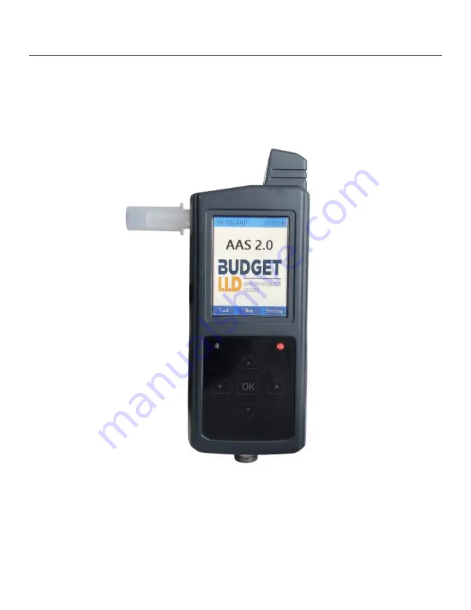
AAS 2.0
User Manual
All rights reserved
Page 1: ...AAS 2 0 interlock user manual Ver 1 0 Breath Alcohol Ignition Interlock AAS 2 0 User Manual All rights reserved ...
Page 2: ... alcohol ignition interlock device utilizing the latest technology providing real time reporting and GPS location services Once the AAS 2 0 is installed in a vehicle the driver must pass a breath alcohol test before starting the engine The car can only be started when the driver has a lower BAC than the set alcohol amount in the device Please note the device will require breath samples at random t...
Page 3: ...ssions for users and admin Admin is able to adjust parameter settings through the Manager Tool Remote and Dynamic Unlock Functions Test Exemption Function Allows for bypass in an emergency Anti Circumvention Detects bypass attempts Connection Mode cable connection between handset and control box 3 Application area Personal safety and accountability Work Vehicle safe driving precaution Public trans...
Page 4: ...and colors clear and intuitive Calibration 6 Months Storage Stores over 2 million measured records including the engine status testing results testing date and time etc Dimension LXWXH Handset 155mmX64mmX37mm Control box 113mmX145mmX37mm Weight Handset 256g 56 lbs Control box cable 750g 1 6 lbs Input voltage 9 36V Measurement units BAC mg 100ml g 100ml mg ml BrAC mg l ug 100ml g 210L Language Mult...
Page 5: ...le must be started within the set time or another breath sample will be required Once the vehicle has been started the handheld will start the countdown to the first rolling retest 7 1 3 Rolling retest process The Rolling Retest process enables random alcohol tests to be conducted in a specified time span set up in Manager Tool or handset e g minimum 10 minutes maximum 30 minutes after the vehicle...
Page 6: ...w is required through a series of beeps and a notification on the display screen The whole process includes four steps device preparation delivering a blow the data analysis and the result display 7 2 1 Initial test When the ignition switch is turned to the on position the device will ask for the initial test There are four steps of an initial test Figure 7 1 Preparation Figure 7 2 Blowing Figure ...
Page 7: ...ot start and after a period of waiting time the second initial test will be generated Figure 7 5 If a sample free start is required you must call for an unlock code Please press the unlock button to begin entering the password Please refer to 8 2 for more details on a sample free start 7 2 2 Random rolling retest After a certain period following the start of engine e g 10 mins to 30mins a rolling ...
Page 8: ... has not been turned back to the ON position in the set time frame the vehicle will enter lock state and control box will enter sleep mode to save power The Control Box will wake up and generate an initial test once the key is turned to ON 8 Handset Tool and Setting When the system starts up the handset will display the boot screen Clicking the left button Tool to enter menu interface as Figure 8 ...
Page 9: ...uired As shown in Figure 8 2 select Unlock without test to enter the sample free start function Press yes when you see the prompt You re using the override emergency bypass function it will be indicated to the admin Input password unlock the device as shown in Figure 8 11 the vehicle can be started Figure 8 9 Figure 8 10 Figure 8 11 Figure 8 12 ...
Page 10: ...manual test to start the car Select Manual test as shown in Figure 8 2 press yes when you see the prompt Enter the password provided by administrator to start a test continue Input password then an alcohol test will be required as shown in Figure 8 14 the vehicle can be started after the test is passed Figure 8 13 Figure 8 14 ...
Page 11: ...n Figure 8 1 press the right button for the settings of the handset Back light can be set and system information can be checked As shown in Figure 9 2 press up and down button to adjust the brightness Press Default to return to original settings Figure 9 1 Figure 9 2 ...
Page 12: ... 6 Please do not paint the device 7 Please do not detach the antenna or replace it with other antenna or objects since this may negatively impact its communication quality 8 Please install the device in a safe place to avoid liquids impact or excessive vibration 9 The device and its accessories are not impervious to water 10 Please use the manufacturers designated accessories The usage of other ac...
Page 13: ......
Page 14: ......