


Overview
8
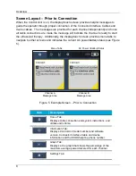
Screen Layout – Prior to Connection
When the Control Unit is on, the display/touch screen provides helpful messages to
guide the operator through proper connection of the Connector Interface Cables and
device cables. The messages are provided for each channel independently and once
all cable connections are made the message will indicate the channel is ready to start
the ultrasound therapy. Additionally, the display/touch screen provides menu tabs to
navigate to other screens and indicates the current AC power/battery status (see Figure
5).
Figure 5. Example Screen – Prior to Connection
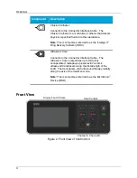
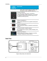
Item
Description
Home Tab:
Displays cable connection and system instructions, and
ultrasound runtime.
Information Tab:
Displays Control Unit model number and software
version, Connector Interface Cable and device
information and the EKOS help line phone number.
Graph Tab:
Displays a line graph that shows the percentage of the
maximum average power delivered for each channel.
Settings Tab:
Menu Tabs
Channel B
Message Area
Channel A
Message Area
AC Power / Battery Status
Summary of Contents for EKOS
Page 65: ...Symbols and Indicators 61 ...