background image

3


Headquarters :

 Konutkent Mah. 3029 Cad. No:3/91 06810 Çankaya Ankara/TURKEY


Phone :

 +90 312 472 42 50


Fax : 

+90 312 502 74 75


Email :

 [email protected]

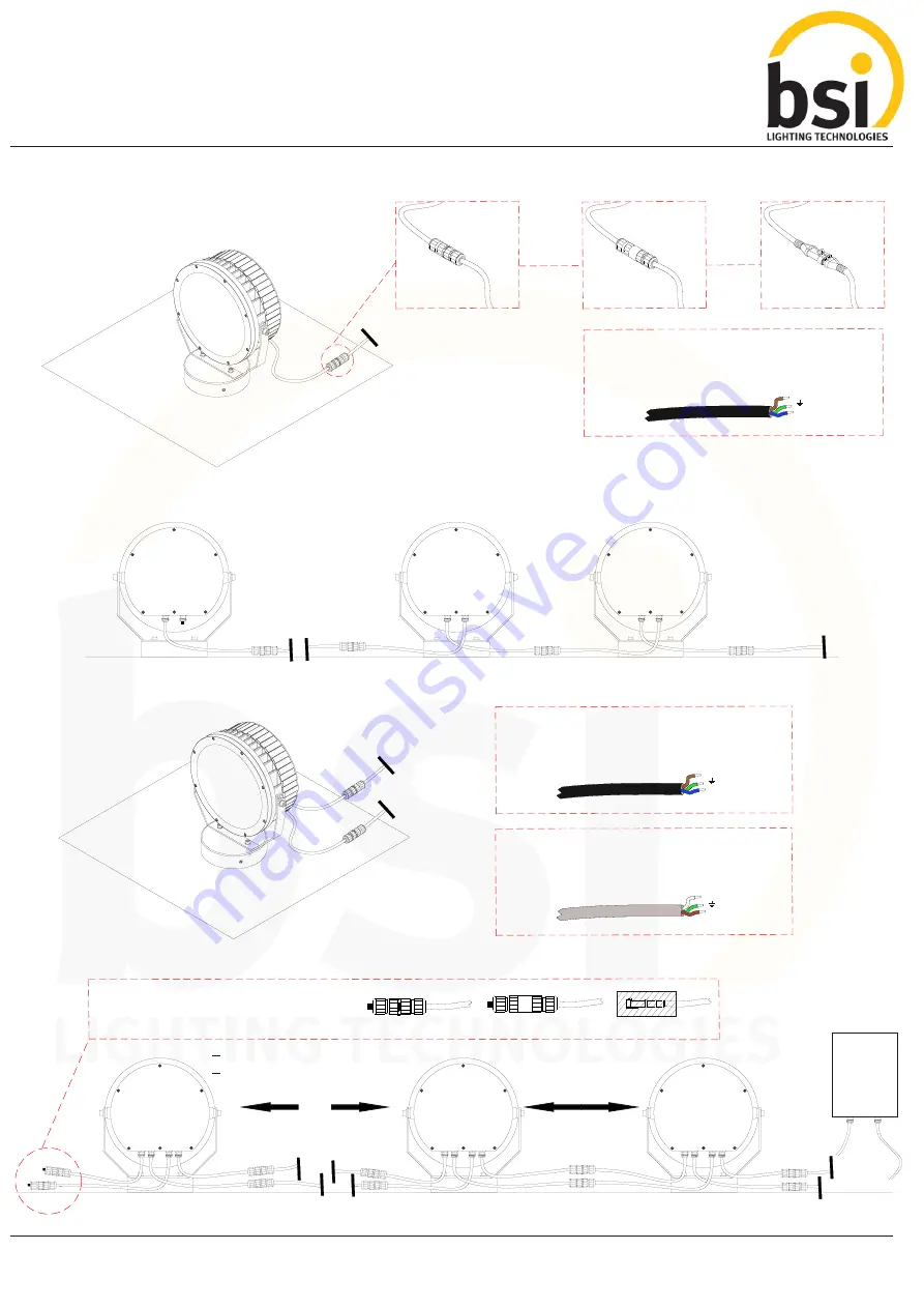
-  Cel a Mono Electr cal Connect on

IP 68 Term nal 
             Block

*Page 4

IP 68 Plug 
         Connector

*Page 5

or

or

IP 68 Socket

When connect ng the
lum na res, make sure that the
same color cables are
match ng.

(L) Brown
(  ) Yellow - Green

(N) Blue

-  Cel a Mono Mult  Electr cal Connect on

220VAC

OUT

220VAC

IN

The  ncom ng power l ne.

-  Cel a RGB-RGBW Electr cal Connect on

220VAC

When connect ng the 
lum na res, make sure that the 
same color cables are 
match ng.

*Please contact us for cables  f  n d fferent colors.

When connect ng the
lum na res, make sure that
the same color cables are
match ng.

*Please contact us for cables  f  n d fferent colors.

DATA

(+) Wh te
(  ) Green

(-) Brown

-  Cel a RGB-RGBW  Mult  Electr cal Connect on

(L) Brown
(  ) Yellow - Green

(N) Blue

CELIA INSTALLATION GUIDE

The  ncom ng 
  power l ne.

220VAC

OUT

220VAC

IN

220VAC

OUT

220VAC

IN

Input Data

Input Electr c

220VAC

DATA

220VAC
OUT  IN

DATA

OUT  IN

Input Electr c

Input Data

220VAC

DATA

220VAC

DATA

220VAC

DATA

220VAC

DATA

220VAC
OUT  IN

DATA

OUT  IN

220VAC
OUT  IN

DATA

OUT  IN

IP 68 Term nal Block IP 68 Plug Connector

IP 68 Socket

RESIN

At the outlet of AC output RESIN cable end of 
the final lum na re, the component  s t ghtened 
as a filled mater al or protected by res n.

DMX Ma n 

Controller

and 

Fuse Box

220VAC

OUT

DATA

OUT

Max 100mt Cable

Max 100mt Cable

Max 160 P ece For RGB
Max 120 P ece For RGBW

Summary of Contents for iCELIA

Page 1: ...es Designed to last in extremely harsh environments RGB RGBW DMX and DALI controllable easy to install with the integrated universal power supply and connect via combined power and data connectors RECOMMENDATIONS FOR THE USER 1 Before the installation make sure that there is no voltage 2 Do not touch the fitting when it is working on switched on 3 Do not look at the fitting directly or from a short ...

Page 2: ...e foot 3 The luminaire is placed on the mounting plate Tighten the setscrews with desired direction by turning right or left CELIA INSTALLATION GUIDE Mount ng Surface 2 Drill holes on the mounting surface and install the fixing plugs The mounting plate is screwed onto the mounting surface Setscrew 4 Allen head cap screws in the left and right side of the luminaire are loosened to the desired angle ...

Page 3: ...n connect ng the lum na res make sure that the same color cables are match ng Please contact us for cables f n d fferent colors DATA Wh te Green Brown Cel a RGB RGBW Mult Electr cal Connect on L Brown Yellow Green N Blue CELIA INSTALLATION GUIDE The ncom ng power l ne 220VAC OUT 220VAC IN 220VAC OUT 220VAC IN Input Data Input Electr c 220VAC DATA 220VAC OUT IN DATA OUT IN Input Electr c Input Data ...

Page 4: ...4 Headquarters Konutkent Mah 3029 Cad No 3 91 06810 Çankaya Ankara TURKEY Phone 90 312 472 42 50 Fax 90 312 502 74 75 Email info bsilighting com CELIA INSTALLATION GUIDE ...

Page 5: ...5 Headquarters Konutkent Mah 3029 Cad No 3 91 06810 Çankaya Ankara TURKEY Phone 90 312 472 42 50 Fax 90 312 502 74 75 Email info bsilighting com CELIA INSTALLATION GUIDE ...

Page 6: ... re through cable and damage the electron c parts ns de The IP68 Connect ng k ts must be assembled n accordance w th the nstallat on nstruct ons Otherw se water may enter to the lum na re through cable and damage the electron c parts ns de The lum na re should not be opened and screws should not be loosened If you want to open the lum na re please contact our company Out of Warranty S tuat ons Ope...

Reviews: