8
Step 4 — Venting
Venting of furnace should be to the outside and in accordance with
local codes or requirements of local utility.
OIL--FIRED APPLIANCES SHALL BE CONNECTED TO
FLUES HAVING SUFFICIENT DRAFT AT ALL TIMES TO
ENSURE SAFE AND PROPER OPERATION OF APPLIANCE.
For additional venting information, refer to ANSI/NFPA 211
Chimney, Fireplaces, Vents, and Solid Fuel Burning Appliances
and/or CSA B139 Installation Code.
This furnace is certified for use with Type “L” vent (maximum flue
gas temperature 575
_
F/302
_
C).
Vent System Inspection
Before furnace is installed, it is highly recommended that any
existing vent system be completely inspected.
CARBON MONOXIDE POISONING HAZARD
Failure to follow this warning could result in personal injury
or death.
The following steps shall be followed for each appliance
connected to the venting system being placed into operation,
while all other appliances connected to the venting system are
not in operation:
1. Seal any unused openings in venting system.
2. Inspect the venting system for proper size and horizontal
pitch, as required in the NFPA31, Installation of Oil Burning
Equipment and the Canadian Standard B140.4 Oil Fired Warm
Air Furnaces.
Determine that there is no blockage or
restriction, leakage, corrosion and other deficiencies which
could cause an unsafe condition.
3. As far as practical, close all building doors and windows
and all doors between the space in which the appliance(s)
connected to the venting system are located and other spaces
of the building.
4. Close fireplace dampers.
5. Turn on clothes dryers and any appliance not connected to
the venting system. Turn on any exhaust fans, such as range
hoods and bathroom exhausts, so they are operating at
maximum speed. Do not operate a summer exhaust fan.
6. Follow the lighting instructions. Place the appliance being
inspected into operation. Adjust the thermostat so appliance is
operating continuously.
7. Test for spillage from draft--hood equipped appliances at the
draft--hood relief opening after 5 minutes of main burner
operation. Use the flame of a match or candle.
8. If improper venting is observed during any of the above
tests, the venting system must be corrected in accordance with
the NFPA31, Installation of Oil Burning Equipment and the
Canadian Standard B140.4 Oil Fired Warm Air Furnaces.
9. After it has been determined that each appliance connected
to the venting system properly vents when tested as outlined
above, return doors, windows, exhaust fans, fireplace dampers,
and any other gas--fired burning appliance to their previous
conditions of use.
!
WARNING
For any chimney or vent, this should include the following:
1. Inspection for any deterioration in chimney or vent. If
deterioration is discovered, chimney must be repaired or
vent must be replaced.
2. Inspection to ascertain that vent system is clear and free of
obstructions. Any blockage must be cleared before
installing furnace.
3. Cleaning chimney or vent if previously used for venting a
solid fuel burning appliance or fireplace.
4. Confirming that all unused chimney or vent connections are
properly sealed.
5. Verification that chimney is properly lined and sized per the
applicable codes. (Refer to list of codes in Safety
Considerations section.)
Masonry Chimneys
This furnace can be vented into an existing masonry chimney. This
furnace must not be vented into a chimney servicing a solid fuel
burning appliance. Before venting furnace into a chimney, the
chimney MUST be checked for deterioration and repaired if
necessary. The chimney must be properly lined and sized per local
or national codes.
If furnace is vented into a common chimney, the chimney must be
of sufficient area to accommodate the total flue products of all
appliances vented into chimney.
The following requirements are provided for a safe venting system:
1. Be sure that chimney flue is clear of any dirt or debris.
2. Be sure that chimney is not servicing an open fireplace.
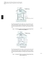
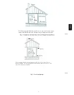
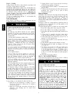
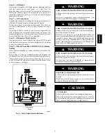
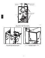
3. Never reduce pipe size below the outlet size of furnace. (See
Fig. 2.)
4. All pipe should be supported using proper clamps and/or
straps. These supports should be at least every 4 ft. (1.2 M)
5. All horizontal runs of pipe should have at least 1/4 in. (6
mm) per ft. (.3 M) of upward slope.
6. All runs of pipe should be as short as possible with as few
turns as possible.
7. Seams should be tightly joined and checked for leaks.
8. The flue pipe must not extend into chimney but be flush
with inside wall.
9. The chimney must extend 3 ft. (.9 M) above highest point
where it passes through the roof of a building and at least 2
ft. (.61 M) higher than any portion of a building within a
horizontal distance of 10 ft. (3.0 M) It shall also be extended
at least 5 ft. (1.5 M) above highest connected equipment
flue collar.
10. Check local codes for any variance.
Step 5 — Factory--Built Chimneys
Listed factory--built chimneys may be used. Refer to chimney
manufacturer’s instructions for proper installation.
UNIT COMPONENT HAZARD
Failure to follow this caution may result in unit component
damage.
This burner is shipped with the oil pump set to operate on a
single
line system. To operate on a
two--line
system the
by--pass plug must be installed. Do not operate a
single
line
system with the by--pass plug installed. Operating a
single
line system with the by--pass plug installed will result in
damage to the pump shaft seal. Pump pressure must be set at
time of burner start--up. A pressure gauge is attached to the
PRESSURE
PORT
for pressure readings. Two
PIPE
CONNECTORS
are supplied with the burner for
connection lines to burner pipe connectors. All pump port
threads are
British Parallel Thread
design. Direct
connection of NPT threads to the pump
will damage
the
pump body. Riello manometers and vacuum gauges
do not
require any adapters, and can be safely connected to the
pump ports. An NPT (metric) adapter (Part no. N05F017)
must be used when connecting other gauge models.
CAUTION
!
374RAN


