background image

20

HYPERION User Manual

Bruker Optik GmbH

Installation 2

2.7.6

Connecting the FPA detector 

Only HYPERION 3000 can be equipped with a FPA detector. 

The following cables are included in the delivery scope of the FPA detector: :

• Signal cable
• Trigger cable 
• Power supply cable (including external power supply unit)

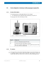
Bottom side of the FPA detector compartment

A

Figure 2.2:

Cable connectors of the FPA detector 

E

D

B

C

Fig. 2.2

Sockets and switches 

A

ON / OFF switch 

B

Outlet of the signal cable 

C

LED

Note:

 This LED lights green when the FPA detector is switched on.

D

Socket for connecting the trigger cable 

E

Socket for connecting the power supply cable

Summary of Contents for HYPERION

Page 1: ...HYPERION User Manual I 24319 ...

Page 2: ... in any form or by any means including printing photocopying microfilm electronic systems etc wit hout our prior written permission Brand names registered trademarks etc used in this manual even if not explicitly marked as such are not to be considered unprotected by trademarks law They are the property of their respective owner This manual is the original documentation for the FT IR microscope HY...

Page 3: ... 13 2 6 2 Safety note 13 2 6 3 Procedure 14 2 7 Cable connections 15 2 7 1 Overview of the connection sockets 15 2 7 2 Connecting the motorized microscope stage 17 2 7 3 Connecting the joystick 18 2 7 4 Connecting the video camera 18 2 7 5 Connecting the MCT detector s 19 2 7 6 Connecting the FPA detector 20 2 7 7 Connecting the microscope to the spectrometer 22 2 8 Connecting the microscope to th...

Page 4: ...uid nitrogen in the detector 60 4 5 Resetting the motorized stage 62 4 6 Checking and correcting the condenser setting 63 4 7 Checking the IR signal intensity 66 4 7 1 Procedure in transmission mode 66 4 7 2 Procedure in reflection mode 68 4 7 3 Procedure with ATR objective 72 4 8 Checking the detector saturation 75 4 9 Viewing the sample and selecting the measurement area 77 4 10 Viewing and meas...

Page 5: ... 116 5 3 1 Overview 116 5 3 2 Heating freezing stage THMS 600 Linkam 117 5 3 2 1 General information 117 5 3 2 2 Controlling the temperature 117 5 3 2 3 Safety notes 118 5 3 3 Heatable sample holder 118 5 3 3 1 General information 118 5 3 3 2 Safety notes 119 5 3 3 3 Controlling the temperature 119 5 4 Polarizer 120 5 4 1 General information 120 5 4 2 Safety notes 120 5 4 3 Installation location 1...

Page 6: ...rk field of view 148 7 2 2 No video image is displayed on the LCD monitor and or in OPUS 149 7 2 3 No IR signal is detected or the detected IR signal intensity is too low 150 7 2 4 IR signal check in OPUS shows an unusual spectrum curve shape 153 7 2 5 Problems regarding the motorized microscope stage 154 7 2 6 Problems regarding the ATR objective 155 7 2 7 Problems regarding mapping measurements ...

Page 7: ...g A safe and trouble free operation of the microscope is ensured only if all compo nents of the analysis system are installed and operated as well as maintained and repaired according to the procedures described in this manual and in compliance with all relevant safety standards and regulation The microscope should be operated only by authorized personnel which is trained in operating the microsco...

Page 8: ...idental contact hazard Do not touch these parts Do not remove any housing part for which you are not authorized Ensure that all live parts do not come into contact with a conductive substance or liquid Crushing hazard due to moving parts This warning symbol indicates a crushing hazard caused by a moving part It is located near or on the moving part in question Keep your hands and other parts of th...

Page 9: ...d take the correspond ing protective measures e g wearing protective clothing masks gloves etc Affix the corresponding warning label at the appropriate place at the microscope The label must be well legible and permanently discernible Waste disposal Dispose all waste produced chemicals infectious and radioactively contaminated sub stances etc according to the prevailing laboratory regulations Dete...

Page 10: ...ce instructions Use only components and accessories supplied by Bruker For components and acces sories made by other manufacturers and used in conjunction with the microscope Bruker Optik GmbH does not assume any liability for safe operation and proper function ing 1 5 Service contact data In case you have questions about safety installation and or operation as well as repair and maintenance of th...

Page 11: ...ripherals refer to the corresponding manuals Important note The operator can reconnect all cables if required for example after having relocated the analysis system For information about the connections refer to the corresponding sections in this chapter 2 2 Inspecting the packaging After having received the microscope inspect the packaging for damages If there are any signs of damage contact ship...

Page 12: ...pdf file on the OPUS CD a The HYPERION microscope is available in three different variants HYPERION 1000 HYPERION 2000 and HYPERION 3000 For information about the available microscope variants see section 3 1 Required components PC compatible data system Note If desired the PC can also be provided by the operating company FT IR spectrometer of the TENSOR or VERTEX series Note The microscope is an ...

Page 13: ...ysis system HYPERION microscope plus FT IR spectrometer plus data station possible acces sories Environmental conditions Ambient temperature range 18 C 30 C 64 F to 86 C Ambient temperature variations max 1 C h and max 2 C day Temperature variations can impair the results of long term measurements Humidity non condensing 70 relative humidity Installation site a closed room max 2000m above sea leve...

Page 14: ...oblems concerning main power supply e g brownouts power surges frequent thunderstorms or power blackouts use an UPS unit Uninterruptible Power Supply to ensure an uninterruptible power supply and conse quently an operation without interruptions Possibilities of inter rupting the mains power supply The mains power supply of the microscope can be inter rupted as follows by disconnecting the safety p...

Page 15: ...te CAUTION Injury and or property damage due to non observance of the following safety instructions regarding the external power supply unit To ensure a safe operation of the external power supply unit observe the following safety instructions If the external power supply unit is damaged disconnect it instantly from the sup ply circuit Never put a damaged external power supply unit into operation ...

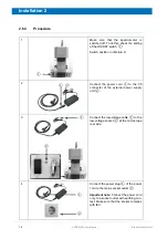
Page 16: ...ition in off state O 2 Connect the power cord to the C5 connector of the external power supply unit 3 Connect the low voltage cable to the low voltage socket at the microscope rear side 4 Connect the power plug of the power cord to the mains socket outlet Important note Connect the power cord only to a socket outlet with earthing con tact Make sure that the socket complies with IEC ...

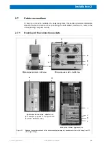
Page 17: ...r etc refer to the corresponding computer manual 2 7 1 Overview of the connection sockets Microscope rear side total view A C D E F B Microscope rear side detail view Spectrometer rear side detail view For example purposes it is a spectrome ter of the TENSOR series Rear side of the supplied PCs Figure 2 1 Relevant connection sockets at the microscope upper images spectrometer lower left image and ...

Page 18: ... spectrome ter and possibly additional accessories e g HTS XT module D DET A socket for connecting the signal transmission cable of the detector in the left detector compartment detector A The detector signal is transmitted to the spectrometer E DET B socket for connecting the signal transmission cable of the detector in the right detector compartment detector B The detector signal is transmitted ...

Page 19: ...the cables labeled X and Y to the corresponding connectors at the right side of the motorized stage Important Make sure that the labeling of the cables corresponds with the labeling of the stage connectors 2 In case the stage is equipped with two motors skip this step In case the stage is equipped with an third motor proceed as follows 1 Connect the cable which is already factory connected to stag...

Page 20: ...PC is switched on connecting the joystick can cause unintentional stage movements 2 7 4 Connecting the video camera 1 Connect the 15 pole D sub connector of the joystick cable to the corresponding male socket at the PC 1 Connect the video signal cable of the video camera to the S VHS socket of the converter box Connect the USB cable of the con verter box to an USB port at the PC ...

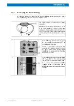
Page 21: ...e into digital signals These digital signals are transmitted to the spectrometer electron ics 1 Connect the signal cable of the standard MCT detector to the socket DET A at the microscope rear side In case the microscope is equipped with a second MCT detector option connect the signal cable of this optional MCT detector to the socket DET B at the microscope rear side 2 Connect the signal cable com...

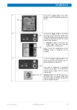
Page 22: ...or Signal cable Trigger cable Power supply cable including external power supply unit Bottom side of the FPA detector compartment A Figure 2 2 Cable connectors of the FPA detector E D B C Fig 2 2 Sockets and switches A ON OFF switch B Outlet of the signal cable C LED Note This LED lights green when the FPA detector is switched on D Socket for connecting the trigger cable E Socket for connecting th...

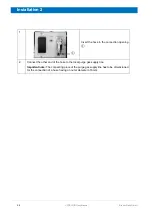
Page 23: ...fore connecting the trigger cable make sure that the spectrometer is switched off Note In case of a spectrometer of the TENSOR series a distributor box is required 3 Connect the power supply cable to the Power socket at the bottom side of the FPA detector compartment The power is supplied by a dedicated external power supply unit Connect this external power supply unit to a mains socket outlet Imp...

Page 24: ...se the modes transmission mode reflection mode and viewing mode measurement mode are to be activated by the corresponding OPUS VIDEO functions and not by pressing the corresponding buttons at the microscope control panel 1 Connect the CAN BUS cable to the CAN BUS socket at the spectrometer rear side and to one of the three CAN BUS sockets at the microscope rear side Note The three CAN BUS sockets ...

Page 25: ... Procedure i The required hose is not included in the standard delivery scope of the microscope It is the operating company s duty to provide a hose PVC outer diameter 6 mm of the required length Make sure that the hose is rated for the indicated operating pressure A B Figure 2 3 Purge gas inlet microscope rear side Fig 2 3 Component A Valve for controlling the purge gas flow rate B Connection ope...

Page 26: ...Insert the hose in the connection opening 2 Connect the other end of the hose to the local purge gas supply line Important note The connecting piece of the purge gas supply line has to be dimensioned for the connection of a hose having an outer diameter of 6 mm ...

Page 27: ...h this microscope variant By default it is equipped with a manually operated microscope stage which allows for single point measurements HYPERION 2000 Advanced variant This variant includes in addition a LCD color monitor and a motorized x y stage instead of a manually operated stage The motorized x y stage allows for per forming mapping measurements HYPERION 3000 Variant for imaging microscopic F...

Page 28: ...elements components Front view A B C D E F Figure 3 1 HYPERION 2000 Front view G Fig 3 1 Component Control element A Control panel B Sample stage motorized stage C Revolving nosepiece with objective s D LCD monitor E Binocular F Video camera G Rotating knobs for focussing the condenser ...

Page 29: ...ating elements of the LCD monitor For detailed information about these operating elements see section 3 11 F Detector comportment housing the optional detector G Koehler aperture control for opening and closing the iris aperture to set the Koehler illumination in the reflection mode H Rotating knobs for focussing coarse and fine focus Note In case of a motorized x y z stage joystick controlled and...

Page 30: ...f the microscope C Rotating knobs for focussing coarse and fine focus Note In case of a motorized x y z stage joystick controlled and com puter controlled focussing is possible The third stage motor for a motor ized stage movement in z direction is an optional feature D Microscope lamp visible light source for reflection microscopy E Detector comportment housing the standard MCT detector F Polariz...

Page 31: ...g activated only spectroscopic measurements can be per formed e g by operating the START button H in fig 3 4 Sample viewing is not pos sible Activating this button automatically deactivates the VIS button and the VIS IR button D Brightness indicator indicates the current brightness intensity of the visible illumi nation in relation to the maximum possible brightness intensity by means of a bar gra...

Page 32: ...urement parameter settings in OPUS Note Before pressing this button make sure that either the IR button or VIS IR but ton is activated the OPUS software program is open and appropriate measurement parameter settings are selected See appendix B in this manual and the OPUS Ref erence Manual Fig 3 4 Control element and explanation Figure 3 5 Adjusting the brightness intensity of the microscope illumi...

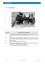
Page 33: ... x and y direction by means of a joystick and the corresponding OPUS functions Optionally a joystick and computer con trolled stage movement in z direction is also possible For information about a joystick controlled stage movement see section 3 5 5 For information about a computer controlled stage movement refer to the OPUS VIDEO Manual and the OPUS MAP Manual With a motorized stage spectroscopic...

Page 34: ...e right assuming the operator stands in front of the micro scope B Rotary knob for moving the stage in y direction Using this knob the stage is moved backward forward assuming the operator stands in front of the microscope C Manual x y stage Note The sample has to be placed over the hole D Rotary knob for moving the stage in z direction Using this knob the stage is moved upward downward for focuss...

Page 35: ...ig 3 7 Control element and explanation A and A Condenser focussing knob to raise or lower the condenser in relation to the sample or sample stage in order to maximize the beam intensity in transmittance mode B and B Coarse focus knob Using this rotary knob the distance between sample and objective is changed in larger increments than with the fine focus con trol C and C Fine focus knob Using this ...

Page 36: ...age needs to be selected For information about how to con figure the mapping device and the imaging device refer to the OPUS VIDEO Manual Figure 3 8 Motorized stage front view B A Fig 3 8 Component and Explanation A Motorized sample stage Note After each computer reboot the motorized stage needs to be reset i e the stage needs to move to its home position x 0 y 0 See section 4 5 B Joystick to cont...

Page 37: ...by the joystick as follows Stage movement in z direction focussing Rotating the joystick clockwise Stage moves downwards Rotating the joystick coun ter clockwise Stage moves upwards When the stage is moved in z direction using the joystick the stage is moved only by the fine drive Stage movement in x direction Tilting the joystick to the right or to the left Stage movement in y direction Tilting t...

Page 38: ...C D C B Fig 3 9 Component and Explanation A Pinhole aperture for adjusting the condenser Note The condenser is adjusted exclusively in the transmission mode B Condenser C and C Condenser focussing knob to raise or lower the condenser in relation to the sample or sample stage in order to maximize the beam intensity in transmittance mode D and D Centering screws to center the condenser by moving it ...

Page 39: ...standard delivery scope Depending on the material of the knife edges there are two types of knife edge apertures available aperture with knife edges made of metal aperture with knife edges made of glass The knife edge aperture with the metal knife edges can be used for measurements in VIS NIR and MIR range whereas the transparent knife edge aperture with the glass knife edges can only be used for ...

Page 40: ...e section 3 7 4 Pinhole aperture for condenser adjustment This aperture is included in the standard delivery scope It is used for adjusted the condenser for transmitted light microscopy and for checking the signal intensity in the transmission For information about how to adjust the condenser see section 4 6 For information about how to check the signal intensity in the transmission mode see secti...

Page 41: ...mission This aperture is opened and closed by a knurled ring which is located below the condenser Attention This aperture is in the IR beam path For this reason do not forget to open the aperture completely before starting a spectroscopic measurement C Installation location for an additional aperture for measurements in reflection used for narrowing down the sample area to be analyzed i e sample a...

Page 42: ... narrowing down the sample area to be analyzed i e sample areas which are not intended for spectroscopic analysis are masked off by the aperture knife edges Note The motorized knife edge aperture is an option It is installed instead of the manual knife edge aperture D in fig 3 10 It is operated exclusively by the OPUS VIDEO software For information about how to operate the motorized knife edge ape...

Page 43: ... by max 360 using the thumbwheels A in fig 3 11 In this case the previ ously set aperture opening size is locked and the knife edge aperture is rotated The rotation center is identical with the center of the viewing field C Lever in back position When the lever is in the back position the distance between two opposite knife edges i e the size of the rectangular aperture opening can be increased or...

Page 44: ...sing this lever the visible light is routed either to the binocular or to the video camera The possible lever positions and their meaning are illustrated in the legend below the light path selector lever See B and C in fig 3 14 B If the lever is pushed in completely the light is routed to the binocular In this case the sample can be viewed only by looking through the binocular C If the lever is pu...

Page 45: ... intend to work Note Depending on the dimensions of the objectives up to four objec tives can be attached at the nosepiece at the same time To place an objective in the optical path do NOT rotate the nosepiece by gripping an objective but the nosepiece itself Rotate the nosepiece until the wanted objective is in the optical path The nosepiece snaps automatically into the exact position i e it clic...

Page 46: ... large objectives e g 15x objective and ATR objective In this case you have to remove one of these two large objectives first 4x objective with glass lens Due to its low magnification it is primarily suitable for obtaining an overview of the sample if the viewing area of a higher magnification objective is not large enough Use this objective for sample viewing only Do not use it for performing IR ...

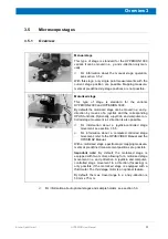
Page 47: ...ght eyepiece there is a cross hairs B Interpupillary scale to facilitate the readjustment of the binocular eyepieces to your individual interpupillary distance The interpupillary scale is on the left eye piece While looking through the binocular increase or reduce the distance between the two eyepieces until you can view the sample comfortably An index mark next to the interpupillary scale indicat...

Page 48: ...ample can be viewed on the LCD monitor also during a IR spectro scopic measurement providing that the VIS IR mode A in fig 3 4 is activated B UP button and DOWN button Use these two buttons to adjust the value of the currently selected parameter e g brightness contrast etc C Menu button to open the menu for adjusting display parameters e g brightness contrast etc for den LCD monitor D Input signal...

Page 49: ... 000 600 cm 1 Optionally the right compartment can be equipped with an second detector The optionally available detectors are listed in section A 5 Figure 3 18 a HYPERION 1000 B A A B b HYPERION 3000 Fig 3 18 Component and description A and A HYPERION 1000 2000 3000 left detector compartment housing the standard MCT detector B HYPERION 1000 2000 right detector compartment housing an optional MCT d...

Page 50: ...tectors available which differ from the standard detector with regard to spectral range detection sensitivity and hold time See section A 5 The MCT detector is a single element detector ele ment size 0 25 mm x 0 25 mm This type of detector is designed for spectroscopic measurements in the mid infrared range FPA detector The FPA detector can be installed in a HYPERION 3000 microscope only The FPA d...

Page 51: ... GmbH HYPERION User Manual Overview 3 3 13 Beam path 11 22 10 19 9 3 8 6 7 25 18 12 5 14b 13a 14a 13b 23 4 16 2 24 21 17 1 20 15 Figure 3 19 HYPERION 1000 and 2000 Beam path in transmission mode and in reflection mode ...

Page 52: ...HYPERION User Manual Bruker Optik GmbH Overview 3 Figure 3 20 HYPERION 3000 Beam path in transmission mode and in reflection mode 1 20 15 21 2 4 23 5 3 12 13a 13b 14a 14b 22 10 11 9 8 6 7 19 24 18 17 16 25 ...

Page 53: ...Dichroic mirror that transmits only fluorescent light for fluorescence option 6 Objective 7 Sample 8 Aperture manual or motorized knife edge aperture to define the sample area for the analysis transmittance or reflectance mode 9 Three position motorized mirror Position 1 Viewing only An opening allows visible light to reach the binocular eye piece or the camera port Position 2 Spectral data acquis...

Page 54: ...meter 21 Three position motorized mirror Position 1 Mirror deflects the IR beam to the transmittance optics Position 2 Mirror deflects the IR beam to the reflectance optics Position 3 No mirror intercepts the IR beam The beam can go to the external acces sory port 22 Video camera port 23 Optional polarizer for reflectance mode either for visible light only or for visible light and IR light two pol...

Page 55: ...ctrometer the microscope can be coupled only to the right as well as to the left spectrometer side In addition to the spectrometer other optional accessories e g external sample cham ber IMAC can be coupled to the left or right IR beam outlet port of the microscope Optionally the IR beam can be passed through the microscope to further accessories Depending on the demands made on the analysis syste...

Page 56: ...54 HYPERION User Manual Bruker Optik GmbH Overview 3 ...

Page 57: ...vice in OPUS OPUS VIDEO Manual measurement parameters appendix B in this manual and the OPUS reference manual how to operate the ATR objective section 4 12 in this manual how to operate the motorized knife edge aperture OPUS VIDEO Manual how to perform continuous scan mea surements with the FPA detector OPUS FPA Manual how to validatea the analysis system i e FT IR spectrometer plus HYPERION micro...

Page 58: ...s at the spec trometer rear side Refer to the user manual of the spec trometer in question 3 Switching on the PC and the monitor For information about this topic refer to the corresponding user manuals Switching on the analysis system Procedure with FPA detector Important When switching on the complete analysis system i e microscope with FPA detector plus spectrometer plus PC always keep to the fo...

Page 59: ... how to cool down the FPA detector see section 4 4 3 Cooling down the FPA detector with liquid nitrogen to its operating tempera ture See section 4 4 4 Switching on the PC and the monitor For information about this topic refer to the corresponding user manuals 5 Switching on the FPA detector The ON OFF switch is at the bottom side of the FPA detector compartment Switching off the analysis system N...

Page 60: ...d down to its operating temperature If not cool down the detector using liquid nitro gen Note The detector temperature warn ing indicator G in fig 3 4 is situated on the operating panel of the micro scope If it lights up red the detector in question needs to be cooled down For information about how to cool down the detector see section 4 4 Resetting the motorized microscope stage to its home posit...

Page 61: ...is inserted in the corresponding opening on the top side of the detector compartment The microscope is delivered with this opening being closed by a plug 4 4 2 Safety notes The temperature of the liquid nitrogen is minus 196 C minus 320 8 F 1 The hold time indicates how long the cooling effect of the liquid nitrogen lasts The available MCT detectors have different nominal hold times 8 12 and 24 ho...

Page 62: ...included in the deliv ery scope 2 Pour slowly liquid nitrogen into the funnel Avoid spilling the liquid nitrogen on the microscope housing Pour liquid nitrogen only in a filling hole underneath which a detector is installed Otherwise the microscope will get dam aged Filling hole for stan dard MCT detector Filling hole for optional MCT detector HYPERION 1000 and HYPERION 2000 HYPERION 3000 Filling ...

Page 63: ...r the liquid nitrogen slowly in the funnel to minimize boiling and splashing Stand clear of boiling and splashing liquid nitrogen and escaping gases Wear suitable protective goggles or a face shield Be aware that liquid nitrogen can squirt out of the detector dewar from time to time during the entire filling process Wait until the funnel is empty before refilling it When the liquid nitrogen stops ...

Page 64: ...low for a hindrance free stage movement If not move the condenser slightly downwards and or the stage upwards Otherwise the condenser may hinder the stage from reaching its home position If the stage does not succeed in reaching its home position due to a hinderance switch off the PC to abort the reset process NOTE Risk of damaging the ATR objective crystal The ATR objective crystal can get damage...

Page 65: ...he 15x objective in the beam path 2 Make sure that the beam path is not obstructed for example by a polarizer a sample or a closed knife edge aperture i e the knife edge aperture has to be open completely 3 Activate the viewing measur ing mode by using the VIS IR button on the operating panel 4 Activate the transmission mode by using the corre sponding button on the operating panel 5 Move the pinh...

Page 66: ...center of the cross hairs then the con denser is set optimally When you see an unsharp image and or the bright cir cle is not aligned to the center of the cross hairs then the condenser height needs to be adjusted and or the con denser needs to realigned in x and or y direction 8 When the check has revealed that the condenser is set opti mally rotate the thumb wheel in the arrow direction of the b...

Page 67: ... the circle is not aligned to the center of the cross hairs move the condenser in x and or y direction using the centering screws in until the circle is correctly aligned to the cross hairs center Attention After having set the con denser correctly do not forget to move the pinhole aperture out of the beam path again by rotating the thumb wheel in the arrow direction of the big cir cle ...

Page 68: ...n you look through the binocular 2 Activate the measuring mode by actuat ing the IR button on the operating panel of the microscope Make sure that the transmission mode is activated 3 Make sure that the beam path is not obstructed for example by a polarizer a sample or a closed knife edge aperture i e the knife edge aperture has to be open completely 4 Open the OPUS software program Select in the ...

Page 69: ...with all optics compo nents being optimally adjusted You will find the test protocol in the folder supply with the microscope 6 If there is not any IR signal detected or if the amplitude value displayed in OPUS deviates significantly from the amplitude value of the supplied OVP test protocol see section 7 2 for possible causes and troubleshooting solutions Note A detected amplitude value above 32 ...

Page 70: ...operating panel of the microscope Activate the reflection mode by actuating the corresponding button on the operating panel of the microscope 4 Place the supplied gold mirror on the microscope stage underneath the objective 5 Make sure that the light path selector lever is pushed in completely i e the light is routed to the binocular 6 View through the binocular and adjust the brightness using the...

Page 71: ...ormation about how to operate the manual knife edge aperture see section 3 7 3 Note 100 microns correspond to 5 scale lines of cross hairs in the binocular but not in the OPUS video view Validated analysis system and pinhole aperture for reflection mode Define the measurement area as shown in the lower image using the pinhole aperture for the reflection mode To do this swing the aperture in the be...

Page 72: ...d to the video camera In case the light path selector lever see in step 5 needs to be pulled out completely 9 Activate the measuring mode by actuat ing the IR button on the operating panel of the microscope 10 Open the OPUS software program Select in the Measure menu the Advanced Measurement function Load an adequate experiment file For information about the available standard experiment files see...

Page 73: ... with all optics compo nents being optimally adjusted You will find the test protocol in the folder supply with the microscope 12 If there is not any IR signal detected or if the amplitude value displayed in OPUS deviates significantly from the amplitude value of the supplied OVP test protocol see section 7 2 for possible causes and troubleshooting solutions Note A detected amplitude value above 3...

Page 74: ...make sure that the stage is low enough If this is not the case first lower the stage 2 Make sure that the beam path is not obstructed for example by a polarizer a sample or a closed knife edge aperture i e the knife edge aperture has to be open completely 3 Activate the reflection mode by actuating the corresponding button on the operating panel of the microscope 4 Bring the ATR crystal in the mea...

Page 75: ...cally by the In focus LED When the ATR crystal has reached the focus position the In focus LED turns from red to green for a short moment Then it goes off 8 Activate the measuring mode by actuat ing the IR button on the operating panel of the microscope 9 Open the OPUS software program Select in the Measure menu the Advanced Measurement function Load an adequate experiment file For information abo...

Page 76: ...th all optics compo nents being optimally adjusted You will find the test protocol in the folder supply with the microscope 12 If there is not any IR signal detected or if the amplitude value displayed in OPUS deviates significantly from the amplitude value of the supplied OVP test protocol see section 7 2 for possible causes and troubleshooting solutions Note A detected amplitude value above 32 0...

Page 77: ...s in transmittance see section 4 10 For measurements in reflec tance see section 4 11 2 Activate the measuring mode by actuating the IR button C in fig 3 4 on the operat ing panel of the microscope 3 Start the OPUS software Select in the Measure menu the Advanced Measurement function Load an adequate experiment file xpm For information about the available standard experiment files see appendix B 4...

Page 78: ...a detector oversaturation In case an oversaturated detector you can close the manual or motorized knife edge aperture somewhat select in OPUS a smaller spectrometer aperture max 3 mm or smaller Note This solution variant involves the potential risk of forgetting to undo this aperture setting afterwards again only in case of HYPERION 3000 insert a beam attenuator in the optical adapta tion box betw...

Page 79: ... objective 6 Focussing on the sample Make that the sample on the stage or the stage itself does not hit the objective while you move the stage upwards for focussing purposes 7 Setting the brightness Set the brightness in such a way that the sample in question is illuminated optimally Always start with a low brightness level and increase it step wise Note The currently set brightness level is indic...

Page 80: ...lens With the 4x objective however spectroscopic mea surements cannot be performed So do not forget to swing an IR objective e g 15x 36x in the beam path before start ing a measurement revolving nosepiece 5 Set the microscope either for sample viewing through the binocular or for video image display Note It is recommended to use the video image displayed on the monitor Light path selector lever A ...

Page 81: ...ivate the transmission mode either the transmission button on the operating panel F in fig 3 4 or in the OPUS video wizard See OPUS VIDEO Manual 10 Move the stage in x and or y direc tion to find a sample area which is of interest to you Manual x y stage Rotary knobs A and B in fig 3 6 Motorized x y stage Joystick and cor responding stage control functions in OPUS See OPUS VIDEO Manual 11 Take a s...

Page 82: ...PUS See OPUS VIDEO Manual 16 Move the pinhole aperture in the beam path If required correct the con denser setting Note When you see a sharp image of a bright circle which is aligned to the center of the cross hairs then the condenser is set correctly After wards move the pinhole aperture out of the beam path again Thumb wheel of the pinhole aperture for setting the condenser A in fig 3 9 condense...

Page 83: ...g stage control functions in OPUS See OPUS VIDEO Manual 20 Check again the condenser setting If required readjust the condenser height Thumb wheel of the pinhole aperture for setting the condenser A in fig 3 9 and the condenser focussing knobs C C in fig 3 9 See section 4 6 21 Start the sample measurement corresponding OPUS function See OPUS VIDEO Manual Afterwards OPUS calculates automatically th...

Page 84: ...lens With the 4x objective however spectroscopic mea surements cannot be performed So do not forget to swing an IR objective e g 15x 36x in the beam path before start ing a measurement revolving nosepiece 5 Set the microscope either for sample viewing through the binocular or for video image display Note It is recommended to use the video image displayed on the monitor Light path selector lever A ...

Page 85: ...6 Motorized x y stage Joystick and cor responding stage control functions in OPUS See OPUS VIDEO Manual 10 Take a snapshot of the video image of the sample corresponding OPUS function See OPUS VIDEO Manual 11 Mask off that sample area which is not intended for spectroscopic analysis Manual knife edge aperture D in fig 3 10 and fig 3 11 Motorized knife edge aperture F in fig 3 10 This aperture is o...

Page 86: ...obs A and B in fig 3 6 14 Focus on a mirror edge or on a scratch of the mirror surface Note The mirror surface needs to be clean Do NOT change the knife edge aperture setting Manual stage and motorized x y stage coarse and fine focus knobs at the microscope B B and C C in fig 3 7 Motorized x y z stage Joystick and corresponding stage control functions in OPUS See OPUS VIDEO Manual 15 Activate meas...

Page 87: ...S See OPUS VIDEO Manual 19 Focus on the sample Manual stage and motorized x y stage coarse and fine focus knobs at the microscope B B and C C in fig 3 7 Motorized x y z stage Joystick and corresponding stage control functions in OPUS See OPUS VIDEO Manual 21 Activate measuring mode either using the IR button on the operat ing panel of the microscope C in fig 3 4 or in the OPUS video wizard See OPU...

Page 88: ...a lint free cloth and a suitable solvent e g ethanol isopro pyl if required Note Risk of damaging the ATR crystal Handle the ATR objective with utmost care Prevent the ATR crystal tip from fitting the microscope stage Especially in the following situations be aware of the potential risk of damage attaching the ATR objective to the revolving nosepiece or removing the ATR objective from the revolvin...

Page 89: ...on the ATR objective at the nose piece with the two recesses point ing towards the two neighboring objective positions at the revolving nosepiece Screw on the objective by rotating the knurled locking ring Note In doing so the ATR objective is not yet attached firmly at the revolving nose piece Finally to attach the ATR objective firmly by inserting the supplied pin in a hole of the knurled lockin...

Page 90: ...he lower position measuring mode Setting the viewing mode Actuate the rocker switch and push the outer casing of the ATR objec tive all the way up at the same time Then release the rocker switch again Setting the measuring mode Actuate the rocker switch and pull the outer casing of the ATR objec tive all the way down at the same time Then release the rocker switch again Attention When setting the ...

Page 91: ...Focussing In viewing mode Proceed as follows 1 Bring the ATR crystal in the viewing mode position i e upper position See section 4 12 4 2 Focus on the sample by moving the stage slowly upwards Attention When moving the stage upwards take care the ATR crystal tip does not hit the stage Potential risk of damaging the ATR crystal Setting a contact pressure level Actuate the rocker switch and pull the...

Page 92: ...TR objective Focussing for the sample measure ment Put the sample on the stage under neath the ATR objective 4 Focus by moving the stage slowly upwards until the ATR crystal is pressed in the focus position by plastic ring or the sample In case of a man ual stage or a motorized x y stage use the fine focus knobs C C in fig 3 7 In case of a motorized x y z stage use the joystick Note The focus posi...

Page 93: ... ATR objective in the beam path Bring the ATR crystal in the viewing mode position i e upper position Set a contact pressure level which is adequate to the degree of hardness of the sample you intend to analyze ATR objective See section 4 12 4 and section 4 12 5 5 Set the microscope either for sam ple viewing through the binocular or for video image display Note It is recommended to use the video ...

Page 94: ...scope of the ATR objective 10 Bring the ATR crystal in the mea suring mode position i e lower posi tion Note Do not change the contact pres sure level you have set in step 4 ATR objective See section 4 12 4 11 Activate the measuring mode at the microscope either using the IR button on the operat ing panel of the microscope C in fig 3 4 or in the OPUS video wizard See OPUS VIDEO Manual 12 Move the ...

Page 95: ...4 16 Activate the viewing mode at the microscope either the VIS button on the operating panel B in fig 3 4 or in the OPUS video wizard See OPUS VIDEO Manual 17 Focus on the sample by moving the stage slowly upwards Manual stage and motorized x y stage coarse and fine focus knobs at the microscope B B and C C in fig 3 7 Motorized x y z stage Joystick and cor responding stage control functions in OP...

Page 96: ...PUS VIDEO Manual 22 Move the stage slowly upwards until the ATR crystal tip contacts the sample and the ATR crystal is pressed in the focus position Note The focus position is indicated acoustically by a beep and optically by the In focus LED When the ATR crys tal has reached the focus position the In focus LED turns from red to green for a short moment Then it goes off Manual stage and motorized ...

Page 97: ... about how to configure the mapping device and the imag ing device refer to the OPUS VIDEO Manual Hardware ATR objective with focus sensor end switch for stage movement in z direction motorized x y z stage with computer controlled focussing assembly option A673 FA Software optional software package OPUS ATR for controlling the stage movement in z direction Mapping device lstepATRMICstage Imaging d...

Page 98: ...al will not hit the stage Attention Potential risk of damaging the ATR crystal 3 4 Place the plastic ring on the stage underneath the ATR objective 3 5 Move the stage slowly upwards until the ATR crystal is in the focus position Note The focus position is indicated acoustically by a beep and optically by the In focus LED When the ATR crystal has reached the focus position the In focus LED turns fr...

Page 99: ...tive See section 4 12 4 6 3 Light path selector lever A in fig 3 14 6 4 Brightness control thumb wheel B in fig 3 5 6 5 Iris aperture for setting the Koehler illumination in reflection E in fig 3 10 6 6 Coarse and fine focus knob B and C in fig 3 7 Note The joystick controlled stage movement in z direction is automatically disabled 6 7 Joystick or corresponding OPUS functions 7 Take a snapshot or ...

Page 100: ...a short moment Then it goes off 3 Then an IR sample spectrum is acquired 4 Afterwards the stage moves downwards in z direction Then the stage moves to the next x y position of the measurement grid and moves upwards until the ATR crystal is in the focus position Then a spectrum is acquired 5 This procedure is repeated at each measurement grid position 6 Afterwards OPUS calculates automatically the ...

Page 101: ...s attached in an exactly aligned manner if the two VIS GIR knobs see fig 4 4 lie on an imaginary line which runs straight from the front to the back side of the microscope Note Only with this alignment of the GIR objective it is ensured that the incident light beam runs exactly from the right to the left When you screw the GIR objective in the thread of the revolving nosepiece however the exact al...

Page 102: ...l mirror and two plane mirrors which are arranged in parallel The two plane mirrors form a pair of which the position can be shifted See section 4 15 3 The following figure shows the arrangement of the mirrors inside the GIR objective ellipsoidal mirror plane mirrors arranged in parallel Figure 4 3 GIR objective Design of the mirror optics ...

Page 103: ...d in such a way that the focal point of the 15x GIR objective is displaced allowing a sample viewing vertically from above with a 15x magnification Measuring mode GIR The plane mirror pair is positioned in such a way that IR beam is reflected on the sample surface at a grazing incidence angle After being reflected from the sample surface the beam impinges on the ellipsoidal mirror The ellipsoidal ...

Page 104: ...is reflected twice from the sample surface These two images will be referred to as the primary image from the first reflection and the secondary image from the second reflection after the light has been reflected from the ellipsoidal mirror The secondary image is both inverted and mirrored relative to the primary image See fig 4 6c Ideally both images should lie one upon the other See fig 4 6b Not...

Page 105: ...ics of the GIR objective to the viewing mode VIS 4 Microscope Activate the reflection mode 5 Microscope Activate the viewing mode 6 Put the mirror on the microscope sample stage Note The mirror is included in the delivery scope 7 Focus on the mirror by moving the stage upwards 8 Move the stage in x and or y direction until you see an edge of the mirror Align the mirror edge vertically Position the...

Page 106: ...n it upside down 2 Remove the bottom part of the objective housing by loosening the two slotted head screws VIS GIR knobs at the long side of the objective and the two slotted head screws at the bottom side of the objective See fig 4 9 Figure 4 8 a GIR mode Image of a vertically aligned mirror edge alignment of the mirror optics is OK Figure 4 8 b GIR mode mirror edge is not vertically aligned ali...

Page 107: ...nd or y direction until you see an edge of the mirror Align the mirror edge vertically Position the mirror in such a way that the vertical mirror edge is more or less in the center of the image See fig 4 7 11 Set the mirror optics of the GIR objective to the measurement mode GIR 12 Rotate the lower part of the GIR objective slightly to the left or to the right fig 4 11 until the displayed image sh...

Page 108: ...Allen screws at the bottom side of the GIR objective See fig 4 10 In doing so do not misalign the mirror optics again 15 Remove the GIR objective from the revolving nosepiece 16 Fit the bottom part of the housing on the objective and fasten it using the four slot ted head screws See fig 4 9 Figure 4 11 Adjusting the orientation of the mirror optics ...

Page 109: ...ive in the beam path Set the mirror optics of the GIR objective to the viewing mode VIS GIR objective fig 4 4 See section 4 15 3 5 Focus on the mirror e g on a mirror edge or on a scratch on the mirror sur face Attention Due to the very small work ing distance 0 7 mm of the GIR objec tive move the stage upwards carefully Prevent the stage from hitting against the GIR objective bottom side Other wi...

Page 110: ...background measurement corresponding OPUS function See OPUS VIDEO Manual 10 Move the stage downwards Exchange the mirror for the sample Manual stage and motorized x y stage coarse and fine focus knobs at the micro scope B B and C C in fig 3 7 Motorized x y z stage Joystick and cor responding stage control functions in OPUS See OPUS VIDEO Manual 11 Set the mirror optics of the GIR objective to the ...

Page 111: ...ully Prevent the stage from hitting against the GIR objective bottom side Other wise the mirror optics of the GIR objec tive might get damaged Manual stage and motorized x y stage coarse and fine focus knobs at the micro scope B B and C C in fig 3 7 Motorized x y z stage Joystick and cor responding stage control functions in OPUS See OPUS VIDEO Manual 15 Set the mirror optics of the GIR objective ...

Page 112: ...ore purging the microscope is recommended espe cially in areas with a high relative air humidity Despite purging the microscope the IR beam is normally exposed to the ambient air in the area between the objective and the sample Optionally you can shield this area for purging purposes as follows by pulling down the plastic shroud of the 15x objective See fig 4 12a by using the optional purge housin...

Page 113: ...sample details can be recognized better than with the objectives included in the standard delivery scope 20x ATR1 objective This objective can be used for both visual sample view ing and IR spectroscopic sample measurements in attenuated total reflection ATR or in reflection For detailed information about the ATR objective and how to operate it see section 4 12 1 ATR objective Attenuated Total Ref...

Page 114: ... sample spectrum has been acquired with p polarized light there is a prominent absorption band at approx 950 cm 1 which results from the aluminum oxide layer on the mirror surface In case of s polarized light however this absorption band does not exist See fig 5 1 As is usual practice for analyzing small sample areas enclose the intended measure ment area using the knife edge aperture In case of t...

Page 115: ... to be analyzed i e sample areas which are not intended for spectroscopic analysis are masked off by the aperture knife edges The motorized knife edge aperture is operated exclusively by means of the OPUS software For information about how to operate the motorized knife edge aperture refer to the OPUS VIDEO Man ual Rotatable wheel aperture The rotatable wheel aperture option can be installed in pl...

Page 116: ... 0 1 20 33 0 60 0 80 0 1 50 42 0 75 0 100 0 1 80 50 0 90 0 120 0 2 10 58 0 10 5 140 0 2 50 69 0 125 0 170 0 3 00 83 0 150 0 200 0 3 75 104 0 187 5 250 0 Aperture diameter in mm Measurement spot diameter in µm with 36x objective Measurement spot diameter in µm with 20x objective Measurement spot diameter in µm with 15x objective Figure 5 2 Aperture locations A B C ...

Page 117: ...erture The aperture installed at this place is used for narrowing down the sam ple area to be measured in transmittance as well as in reflectance Note By default the manually operated knife edge aperture with trans parent knife edges is installed at this place B By default no aperture is installed at this place If required however one of the following apertures can be installed at this place manua...

Page 118: ...ge can be used conjunction with the 15x objective in transmission and reflection as well as with the 36x objective in reflection See section 5 3 2 For more detailed information refer to the documentation accompanying the stage THM S 600 Linkam Heatable sample holder This sample holder can be heated samples up to 180 C 356 F It can be used for IR spectroscopic measurements in transmission as well a...

Page 119: ...a see section A 6 5 3 2 2 Controlling the temperature Temperatures above ambient temperature are realized by the connected heating unit Linkam Cooling down and temperatures below ambient temperature are achieved by pumping liquid nitrogen through the heating cooling block of the stage For more detailed information about this topic refer to the documentation accompanying the stage THM S 600 Linkam ...

Page 120: ... in conjunction with both the manually operated and the motorized microscope stage See fig 5 4a Note Note In case of the motor ized microscope stage the heatable sample holder fits in the cut out of the microscope stage For measurements with the heatable sample stage Bruker recommends using only the 15x objective The sample is placed in the round opening of the sample holder This opening has a dia...

Page 121: ...he spectra if the temperature has been controlled by the OPUS software Measurements during temperature ramps are only possible with the OPUS measurement function Protein Dynamics optional software package OPUS PRO Figure 5 4 a Heatable sample holder placed on the microscope stage Figure 5 4 b Temperature controller CAUTION Risk of burn injuries caused by touching the heatable sample holder Do not ...

Page 122: ...n the beam path In case you want to analyze the sample with non polarized light pull the polarizer holder out of the microscope i The IR polarizer A675 P requires a holder for visible light A675 because this holder has a rotatable mount for the IR polarizer If you have purchased the IR polarizer A675 P separately you have to insert the IR polarizer with the correct orientation into the rotatable m...

Page 123: ...s usually one IR polarizer is sufficient The IR polar izer can be inserted into any slot A B or C in fig 5 6 The polarizer holders are interchangeable They can be inserted into any slot A B or C in fir 5 6 WARNING Health hazard because of improper handling of broken polarizer mate rial Non observance of the following safety instructions could result in death or serious health problems e g poisonin...

Page 124: ...can be rotated using thumbwheel D in fig 5 5 to permit polarized light to pass only in a certain direc tion If the two polarizers are crossed i e their polarization directions are perpendicu lar to each other an isotropic sample such as liquid will appear black An anisotropic sample e g an oriented polymer or many crystalline materials will appear brightly col ored In transmitted light a single vi...

Page 125: ...urpose a sample holder for transmission measurements is included in the delivery scope Optionally additional accessories with QuickLock baseplate are available which can placed in the IMAC sample compartment for example reflection unit A517 P Q for reflection measurements and ATR unit A529 S Q for attenuated total reflection measurements IMAC is designed for a right side coupling to the microscope...

Page 126: ...w A683 These compression cells are used compress and flatten the sample material e g rub ber plastics polymers to an uniform thickness across the measuring area to ensure maximum signal throughput without oversaturating the detector Figure 5 8 HYPERION 3000 coupled to IMAC and FT IR spectrometer Beam attenuator Optical adaptation box Note This box is only required for coupling a HYPERION 3000 micr...

Page 127: ...l available detectors are installed on a special base plate which ensures a precise installation of the detector A realignment is not required The removal and installation procedure of the MCT detector and the FPA detector differ from each other 6 2 2 Removal and installation procedure of the MCT detector NOTE Damage to ESD sensitive electronic components because of accidental electrostatic discha...

Page 128: ...d remove the housing Step 3 Disconnect the ground cable from the detector Step 4 Disconnect the cable of the temper ature sensor from the detector Step 5 Disconnect the data cable from the detector Fastening screw of the left detec tor compartment housing Fastening screw of the right detec tor compartment housing Ground cable yellow green Cable of the temperature sensor white brown Data cable gray...

Page 129: ... compartment 2 Fasten the detector base plate 3 Reconnect all cables to the MCT detector 4 Reinstall the detector compartment housing 5 Switch on the spectrometer Step 6 Loosen the two mounting screws at the base plate of MCT detector using an Allen wrench 3 mm Step 7 Remove the MCT detector carefully from the detector compartment Caution Be careful not to dam age the mirrors Mounting screws ...

Page 130: ...e six fasten ing screws Allen screws using an Allen wrench 2 mm and remove the hous ing Step 3 Disconnect all cable at the rear side of the FPA detector Step 4 Loosen the three mounting screws at the base plate of the FPA detector Note For loosening the two front screws use an Allen wrench 5 mm The back screw is factory equipped with a kind of screw driver Step 5 Remove the FPA detector from the d...

Page 131: ...m the above steps in reverse order 1 Insert the FPA detector into the detector compartment Make sure that the detector base plate snaps into the guide rail 2 Fasten the detector base plate 3 Reconnect all cables to the FPA detector 4 Reinstall the detector compartment housing 5 Switch on the FPA detector ...

Page 132: ...The dewar vacuum is restored by evacuating the detector dewar with a vacuum pump For this purpose the MCT detector needs to be removed from the microscope 6 3 2 Evacuating the MCT detector dewar Required evacuating equipment Vacuum pump turbo molecular pump or oil free high vacuum pump that is capa ble of generating a vacuum of at least 10 5 mbar Adapter for connecting the vacuum pump to the MCT d...

Page 133: ... connecting piece of the adapter has an OD of 9 7mm In addi tion install a shut off valve between adapter and vacuum pump 3 Make sure whether the shut off valve is closed Switch on the vacuum pump Leave the pump running until it has reached its operating temperature 4 Inspect the O ring inside the adapter C in fig 6 3 for signs of wear The O ring inside the adapter is a wearing part that needs to ...

Page 134: ...e section between vacuum pump and detector at first To do this open the shut off valve If a vacuum of 10 4 mbar is generated within a few minutes it is an indication of the leak tightness of this section 10 Close the shut off valve again 11 Screw the threaded rod of the adapter D in fig 6 3 in the connection thread of dewar evacuation valve by turning the adapter knob G in fig 6 3 clockwise 2 to 3...

Page 135: ...e section between vacuum pump and adapter 17 Pull the knob G in fig 6 3 to the open position Attention Make sure that the seal ing plug of the evacuation valve is NOT pulled out This may occur when you have screwed the threaded adapter rod too far in the connection thread of the dewar evacuation valve See step 10 In this case repeat the dewar evacuation If you do not succeed in closing the evacuat...

Page 136: ...r and Maintenance 6 Fig 6 3 Components of the connecting adapter A Coupling nut B O ring retainer C O ring D Threaded rod to remove the valve closure of the detector dewar E Connecting piece for vacuum pump OD 9 7mm F Washer and O ring packing G Knob ...

Page 137: ...TR crystal in the viewing mode position i e upper position if not yet done See section 4 12 4 3 Put the supplied mirror on the microscope stage Position the mirror below the ATR crystal 4 Move the stage carefully upwards until the distance between ATR crystal tip and stage is approx 2 mm Note Risk of damaging the ATR crystal Handle the ATR objective with utmost care Prevent the ATR crystal tip fro...

Page 138: ...case of a damaged ATR crystal the complete assembly i e holder with crystal needs to be replaced As the very small fastening elements screws washers springs and pins may easily get lost during the replacement of the crystal assembly a complete set of mounting hard ware as spare parts is included in the delivery scope of the replacement crystal as well NOTE Do not view through the binocular while m...

Page 139: ...ointing upwards Required tools small flat tip screwdriver tweezers Note They are in the tool box supplied with the microscope hex wrench Note This hex wrench is included in the delivery scope of the ATR crystal 1x set of mounting hardware Crystal assembly Figure 6 5 Replacement ATR crystal Delivery scope Step 1 Loosen and remove the three slotted head screws at the outer ring using a small flat ti...

Page 140: ...his facilitates removing the springs Take the two springs and the pins out of the recesses using the tweezers Caution The springs may jump out of the recess Therefore shield the bot tom side of the objective with your hand Step 5 Remove the crystal assembly and insert the replacement crystal assem bly When inserting the replacement crys tal assembly pay attention to the ori entation of the inner r...

Page 141: ...his place This facilitates inserting the springs Thread the two short pins to the eye lets of the spring Insert the pins in the corresponding recesses of the inner and outer ring Repeat this procedure with the second spring Step 9 Install the three washers and the three slotted head screws at the inner ring Tighten the screws only loosely Do not yet tighten them firmly Note Do not tighten these sc...

Page 142: ...r in vertical direction the ATR objective needs to be attached at the revolving nosepiece and connected to the microscope For information about how to attach the ATR objective to the revolving nosepiece and how to connect the ATR objective to the microscope see section 4 12 3 Step 10 Adjust the crystal assembly in such a way that the distance between the inner ring and the out ring is more or less...

Page 143: ...ly by a beep and optically by the In focus LED When the ATR crystal has reached the focus position the In focus LED turns from red to green for a short moment Then it goes off 5 Move the microscope downwards a little bit Do not change the position of the mirror on the stage 6 Set the ATR crystal in the viewing mode position i e upper position See section 4 12 4 7 Focus on the mirror If the imprint...

Page 144: ...ontal plane by rotating the adjusting screws fig 6 7 using the hex wrench In doing so the crystal assembly is moved in the corresponding direction in horizontal plane The direction in which the crystal assembly needs to be moved depends on the position of the crystal tip imprint in relation to crosshairs center An example is shown in fig 6 6b 2 Recheck the ATR crystal position for centrality See s...

Page 145: ...g concentrically under neath the ATR objective 8 Microscope Activate the measurement mode using the IR button on the micro scope operating panel C in fig 3 4 9 Microscope Activate the reflection mode using the reflection mode button on the microscope operating panel E in fig 3 4 10 Start the OPUS software Select in the Measure menu the Advanced measurement function In the Measurement dialog click ...

Page 146: ... screw for adjusting the height setting of the ATR crystal is situated at the ATR objec tive top side next to the In focus LED cable outlet See fig 6 10a Correct the height setting of the crystal i e adjustment of the ATR crystal position in z direction with the ATR objective being attached at the revolving nosepiece and being placed in the beam path Required tools hex wrench Note This hex wrench ...

Page 147: ...wly upwards until the plastic ring pushes the ATR crystal in the focus position Note The focus position is indicated acoustically by a beep and optically by the In focus LED fig 6 9a When the ATR crystal has reached the focus position the In focus LED turns from red to green for a short moment Then it goes off 8 While watching the signal display in OPUS fig 6 9b correct the height setting of the A...

Page 148: ...146 HYPERION User Manual Bruker Optik GmbH Repair and Maintenance 6 ...

Page 149: ...trometer being the trouble source consult the chapter Troubleshooting in the HYPERION User Manual Depending on how a microscope problem becomes apparent they are dived in the fol lowing categories Sample viewing through the binocular No field of view or dark field of view No video image displayed on the LCD monitor and or in OPUS Problems regarding the motorized microscope stage Problems regarding...

Page 150: ...te the viewing mode VIS using either the VIS button B in fig 3 4 or the VIS IR but ton A in fig 3 4 on the operating panel Depending on whether you have placed a transparent sample or a reflecting sample in the beam path the wrong mode transmission or reflection is activated In case of a transparent sample activate the transmission mode by using the transmission mode button F in fig 3 4 In case of...

Page 151: ...ler illumination in transmission mode is closed Open the iris aperture for setting the Koehler illumination in transmission mode B in fig 3 10 See section 3 7 4 Possible cause Solution Sample is not in focus Focus on the sample Sample does not reflect light at all or has a very poor light reflecting capacity In search of a sample area with better reflec tive characteristics move the microscope sta...

Page 152: ...ic analysis Reason It is a glass objective and glass absorbs mid infrared light Swing an objective in the beam path which is qualified for IR spectroscopic analysis e g 15x objective 36x objective In case of the MCT detector the detector tem perature is too high Note In this case the detector temperature warning indicator on the operating panel G in fig 3 4 lights up red Cool down the MCT detector...

Page 153: ...rized light place the IR polarizer in the beam path See section 5 4 The beam path is blocked by one or more apertures e g knife edge aperture iris aper ture for setting the Koehler illumination pinhole aperture for condenser adjustment Open the aperture s until you get a satisfying IR signal intensity For an overview of the apertures see sec tion 3 7 The aperture situated in FT IR spectrometer whi...

Page 154: ...is closed Open the iris aperture for setting the Koehler illumination in transmission mode B in fig 3 10 See section 3 7 4 Condenser is not aligned properly Check the condenser setting and correct it if required See section 4 6 Sample has a very low light transmitting capacity Use a thinner sample or flatten the sample using a compression cell Note Compression cells are available as optional compo...

Page 155: ...l in the measuring mode position i e lower position See section 4 12 4 Height of the ATR crystal i e crystal position in z direction is not set optimally Correct the height setting of the ATR crystal i e alignment of the ATR crystal position in z direction See section 6 4 7 ATR crystal is dirty Clean the ATR crystal See section 4 12 2 Possible cause Solution Detector is oversaturated For informati...

Page 156: ...properly e g plug fits loosely in connector socket Check the cables for correct connection Connect them correctly See section 2 7 2 The motorized stage moves in an unanticipated manner The cable for controlling the stage movement in x direc tion and the cable for control ling the stage movement in y direction have been mixed up Connect these cables to the corresponding sockets See section 2 7 2 Jo...

Page 157: ...section 4 12 4 Height of the ATR crystal i e crystal position in z direction is not set optimally Correct the height setting of the ATR crystal i e alignment of the ATR crystal position in z direction See section 6 4 7 ATR crystal is dirty Clean the ATR crystal See section 4 12 2 The IR signal check in OPUS reveals that the focus position of the ATR crystal and the ATR crystal position at which th...

Page 158: ...ive remove the plas tic sleeve of the 15x objec tive See section 4 12 3 The IR spectroscopic mea surement does not yield a sample spectrum ATR crystal is damaged Check the ATR crystal for damages See section 6 4 2 If the check reveals that the ATR crystal is damaged replace the crystal assembly For the order number of a replacement crystal see appendix C For informa tion about the replace ment pro...

Page 159: ... tip with the ATR crystal being in the measuring mode posi tion was more than 2 mm Abort the measurement Move the stage upwards until the distance between sample and crystal tip is 2 mm Restart the mapping measurement Hardware Setup in OPUS The wrong stage has been selected in the setup of the Mapping Device and Imaging device OPUS Both in the mapping device setup and in the imaging device setup s...

Page 160: ...ogram Switch off the PC 2 Switch off the FPA detector Note The ON OFF switch at the FAP detector bot tom side See section 4 2 3 Cool the FPA detector with liquid nitrogen See section 4 4 4 Switch on the PC 5 Switch on the FPA detector The IR beam is directed to the MCT detector in the left detector compartment and not to the FPA detector in right detector compartment Note Each time the microscope ...

Page 161: ...r bot tom side See section 4 2 3 Open the OPUS program Select again in the Measure menu the Continuous Scan FPA Measurement function Possible cause Solution Data have been acquired up to the convolution limit of 3900 cm 1 without the optical filter Insert the optical filter in the optical adaptation box See fig 7 1 A VIS polarizer has been in the beam bath dur ing the IR spectroscopic measurement ...

Page 162: ...Figure 7 1 HYPERION 3000 with FPA detector coupled to a FT IR spectrometer by means of an optical adaptation box Optical adaptation box Note This box is only required for coupling a HYPERION 3000 micro scope to a FT IR spectrometer Optical filter Beam attenuator ...

Page 163: ...ea covered by the measure ment Optimized for a diameter of 250 µm Minimum diameter of 10 µm with the standard objective Ambient requirement Ambient temperature range 18 C 30 C 64 F 86 F Temperature variations during a measurement max 1 C Humidity non condensing 70 relative humidity Installation site in a closed room 2000 m above sea level Power supply Voltage 100 240 VAC 10 50 60 Hz Power consumpt...

Page 164: ...ive specific parameters Specification ATR crystal material Ge refraction index 4 Si refraction index 3 4 Contact pressure 0 5 to 8 Newton Five different pressure levels can be set pres sure level 1 contact pressure 0 5 N for very soft samples up to pressure level 5 contact pressure 8 N for very hard samples ATR crystal tip diameter ca 100 µm Parameter Specification max travel range in x and y dire...

Page 165: ...D 4x10 10cm Hz1 2W 1 optionaler MCT detector broad band D315025 with liquid N2 8 h 10 000 450 cm 1 D 5x10 9cm Hz1 2 W 1 optionaler MCT detector broad band D315025M with liquid N2 12 h 10 000 450 cm 1 D 5x10 9cm Hz1 2W 1 InSb detector optional near infrared region D413 with liquid N2 8 h 10 000 1 850 cm 1 D 1 5x10 11cm Hz W InGaAs detector optional D424 3 No cooling required Detector operates at am...

Page 166: ...pical hold time when in operation 8 h typical hold time when not in operation 20 h photovoltaic MCT FPA detector 4 096 elements square arrangement of the elements 64 x 64 4 500 900 cm 1 with liquid N2 typical hold time when in operation 8 h typical hold time when not in operation 20 h Parameter Specification Temperature range 196 C to 600 C Heating rates between 0 1 min and 130 C min max Temperatu...

Page 167: ...ecification max temperature 180 C Temperature variations 1 C at 150 C max diameter of the sample position 13 mm Dimension of the heatable sample holder 75 mm x 50 mm x 10 mm Dimension of the temperature controller 260 mm x 150 mm x 270 mm Cable length 50 cm Power supply requirements 230V 100W 50 60Hz ...

Page 168: ...166 HYPERION User Manual Bruker Optik GmbH Specifications A ...

Page 169: ...ts with the HYPERION microscope In the delivered experiment files the default parameter settings are store If required they need to modified File name of the supplied xpm files For measurements with HYPERION 1000 HYPERION 1000_ATR xpm with ATR objective HYPERION 1000_REFL xpm in reflection HYPERION 1000_TRANS xpm in transmission For measurements with HYPERION 2000 HYPERION 2000_ATR xpm with ATR ob...

Page 170: ...ctive measurement with FPA detector2 you intend to perform 3 Select the corresponding parameter options See the following sections 4 Save the modified parameter settings To do this click in the Video assisted Mea surement dialog on the Advanced tab On this dialog page click on the Save button Note It is advisable to save the modified experiment file with a different file name Information about the...

Page 171: ...roscope but only by the OPUS software Source setting MIR Note This parameter refers to the IR source in the FT IR spec trometer Beamsplitter Select the beamsplitter which is currently situated in the beam splitter operating position FT IR spectrometer Optical filter setting OPEN Note This parameter refers to the optical filter in the FT IR spec trometer Aperture setting 6 mm Note This parameter re...

Page 172: ...170 HYPERION User Manual Bruker Optik GmbH Measurement parameters B ...

Page 173: ...frared region up to 900 cm 1 Dimensions 20 mm x 20 mm thickness 1 mm Pack of 5 pieces A682A Plane mirror aluminum coated Dimensions 30 mm x 24 mm x 3 mm Pack of 5 mirrors A682G Plane mirror gold coated Dimensions 30 mm x 24 mm x 3 mm Pack of 5 mirrors A697 R10 Ge crystal replacement ATR crystal assembly for ATR objective in case of HYPERION 1000 and HYPERION 2000 A697 R10B Ge crystal replacement A...

Page 174: ...172 HYPERION User Manual Bruker Optik GmbH Spare parts and consumables C ...

Page 175: ...173 Bruker Optik GmbH HYPERION User Manual D System diagram ...

Page 176: ...174 HYPERION User Manual Bruker Optik GmbH System diagram D ...

Page 177: ...ning 86 Measuring mode position 72 88 Viewing mode position 88 B Beam attenuator 76 123 124 158 159 160 Beam path 49 HYPERION 1000 and 2000 49 HYPERION 3000 50 Binocular 26 29 42 45 51 64 68 Brightness Setting 77 Brightness control 27 30 Brightness indicator 29 30 C Coarse focus 27 33 Coarse focus knob 33 Compression cell 124 149 152 Condenser 26 28 33 36 52 63 149 152 Centering screws 36 65 Check...

Page 178: ...6 L LCD monitor 25 26 27 29 46 149 150 LED display of the switching status 46 Menu button 46 ON OFF switch 46 Operating elements 27 Light path selector lever 42 64 68 148 149 Liquid nitrogen 59 Safety notes 59 Low voltage socket 14 M Manual knife edge aperture 40 69 115 Manual stage 31 32 162 Control elements 32 Travel range 162 MCT detector 28 30 47 48 125 130 150 163 Cooling 59 Dewar vacuum 130 ...

Page 179: ...iniature 116 Site requirements Environmental conditions 11 Space requirements 11 Spectral range 161 Spectral resolution 161 Stage 26 manually operated stage 25 motorized x y stage 25 Overview 116 Stage movement Joystick controlled 35 Start button 29 30 Switch on procedure with FPA detector 56 Switch on procedure without FPA detector 56 T Transmission mode 77 Viewing and measuring a sample 78 Trans...

Page 180: ...HYPERION User Manual Bruker Optik GmbH ...

Reviews: