297
Trim and Tilt
Troubleshooting
13
Symptoms Chart
If any of these symptoms describe the unit, follow
the indicated Service Procedures, in the order
listed, to locate and correct the problem.
Service Procedures
STEP 1
Be sure the manual release valve is closed. If
NOT, torque to 45 to 55 in. lbs. (5 to 6 N·m).
STEP 2
Temporarily install a known good manual release
valve and retest. If symptoms remain, original
valve is not the problem. Reinstall original valve.
If symptoms disappear, the original valve was
faulty. Remove temporary valve and replace with
correct new valve.
STEP 3
on p. 112 to determine
if problem is power supply.
STEP 4
Remove trim motor and check condition of drive
coupling. If coupling is damaged, replace it.
STEP 5
Temporarily install a known good pump manifold
assembly and retest. If symptoms remain, original
assembly is not the problem. Reinstall original
assembly.
If symptoms disappear, the original pump mani-
fold assembly was faulty. Remove temporary
assembly and replace it with correct one.
STEP 6
Install replacement pump manifold assembly and
retest. If all symptoms are not corrected, recon-
sider the problem using the new symptoms.
STEP 7
Install O-ring kit. Look for any cylinder damage.
Look for chips in fluid or impact valves. Look for
other abnormal conditions. If all symptoms are not
corrected, reconsider the problem using the new
symptoms.
Pressure Leakdown Test
Before servicing a hydraulic unit, it should be
pressure tested to determine the unit's malfunc-
tion. This test must be performed with the hydrau-
lic unit removed from the outboard and mounted
in a vise or holding fixture.
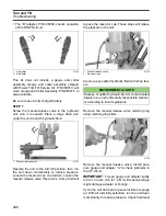
Power Trim/Tilt Service Kit, P/N 434524, allows
testing of trim/tilt operation and component condi-
tion.
•
The “A” adapter, P/N 336658, checks operation
of the UP circuit.
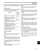
Symptom
Service
Proce-
dures
Unit will not move in either direc-
tion.
1, 2, 3, 4,
6
Unit runs slowly in one direction,
normal speed in other direction.
1, 2, 6
Unit runs slowly. (if low hours)
(if high hours)
1, 2, 7
1, 2, 5, 7
Unit leaks DOWN and/or will not
hold trim position against thrust in
forward.
1, 2, 6
Unit leaks both UP and DOWN –
Leaks down in tilt range and/or will
not hold trim position against thrust
in forward or reverse.
1, 2, 7
Unit will not trim/tilt one way, but
works the other way. Unit will not
run DOWN, but runs UP; or it runs
DOWN, but will not run UP.
2, 3, 6
Summary of Contents for EVINRUDE E-TEC BE225HGXABA
Page 163: ...Oiling System Oil Supply Diagrams 163 8 008208R Port Side View Starboard Side View ...
Page 165: ...Oiling System Oil Supply Diagrams 165 8 008432R Port Side View Starboard Side View ...
Page 167: ...Oiling System Oil Recirculation Diagrams 167 8 008207R Starboard View Port View ...
Page 251: ...Powerhead Powerhead Views 251 11 Powerhead Views Port Hose Routings 3 3 L models 007153 ...
Page 252: ...252 Powerhead Powerhead Views Starboard Hose Routings 3 3 L models 007154 ...
Page 253: ...Powerhead Powerhead Views 253 11 Port Hose Routings 3 4 L models 008503 ...
Page 254: ...254 Powerhead Powerhead Views Starboard Hose Routings 3 4 L models 008502 ...
Page 255: ...Powerhead Powerhead Views 255 11 Port 3 3 L models 008448 ...
Page 256: ...256 Powerhead Powerhead Views Starboard 3 3 L models 008449 ...
Page 257: ...Powerhead Powerhead Views 257 11 Port 3 4 L models 008441 ...
Page 258: ...258 Powerhead Powerhead Views Starboard 3 4 L models 008442 ...
Page 259: ...Powerhead Powerhead Views 259 11 Front 3 3 L models 008450 ...
Page 260: ...260 Powerhead Powerhead Views Front 3 4 L models 008439 ...
Page 261: ...Powerhead Powerhead Views 261 11 Rear 3 3 L models 007142 ...
Page 262: ...262 Powerhead Powerhead Views Rear 3 4 L models 008440 ...
Page 263: ...Powerhead Powerhead Views 263 11 Top 008438 ...
Page 264: ...264 Powerhead Powerhead Views Starboard ICON models 008504 ...
Page 269: ...Midsection Service Charts 269 12 Muffler 004117R ...
Page 320: ...S 322 ...

