


5-6
Confidential
5.1.4.2
Creating of Head Calibration Data and Writing it into Flash ROM
(Function code 02)
Function
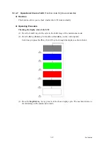
This procedure scans the "Print pattern for creating head calibration data" sheet (see
placed on the scanner glass of the document cover, creates the head calibration data using the
scanning result, and writes it into the flash ROM on the main PCB.
Operating Procedure
Notes
•
Before proceeding to the procedure given below, use Function code 55 (described in
Section 5.1.4.15 "Acquisition of White Level Data and CIS Scanner Area Setting
(Function code 55)"
). If not, this function may fail to create head calibration data
correctly.
•
Make sure that all of the scanner cover (scanner unit), document cover and ADF cover
are closed.
•
For higher precision of uneven printing correction, use the recording paper specified
below to print the "pattern for creating head calibration data."
US: Xerox 4200DP 20 lb., Brother BP60PL
EU, AP and others: Xerox Business 80 g/m
2
, Brother BP60PA
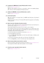
(1) Drag and drop the "head_calib.prn" onto the Brother Maintenance USB Printer driver icon
in the Filedrgs window.
The machine displays the "RECEIVING DATA" on the LCD and prints out "Print pattern
for creating head calibration data" (see
Tip:
Using Function code 61 (
Section 5.1.4.18 "Printout of PRN/JPEG Files in Memory
) also prints out the print pattern. After printing with a memory
card, be sure to remove the card and then proceed to the steps below.
Note:
Make sure that the USB cable is disconnected.
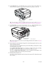
(2) Set the print pattern on the scanner glass of the document cover.
Note:
If the print pattern has been printed on A4-size paper, set the paper approximately 3
mm to the front from the document guidelines. Improper setting results in an error (Error
code 01).
(3) Press the
0
and
2
keys in this order in the initial stage of the maintenance mode.
The "MAINTENANCE 02" and "Set Sheet on FB?" appear on the LCD in this order.
Note:
Pressing the
Stop/Exit
key immediately returns the machine to the initial stage of the
maintenance mode without creating head calibration data.
(4) Press the
Black Start
(
Mono Start
) key.
The machine displays the "Scanning" on the LCD and starts scanning the "Print pattern for
creating head calibration data" placed on the scanner glass.
Upon completion of scanning, the machine displays the "Write Head Calib" on the LCD,
creates the head calibration data, and writes it into the flash ROM on the main PCB.
Upon completion of writing, the "Complete" appears. Press the
Stop/Exit
key to return to
the initial stage of the maintenance mode.
Note:
If an error occurs, the machine beeps and displays "Error No **" on the LCD. Press
the
Stop/Exit
key to return to the initial stage of the maintenance mode and then recover
the machine from the error state, following the table given on the next page. Then go back
to step (2).
Summary of Contents for MFC-J6510DW
Page 15: ...xii Confidential ...
Page 16: ...xiii Confidential ...
Page 17: ...xiv Confidential ...
Page 18: ...xv Confidential ...
Page 19: ...xvi Confidential ...
Page 128: ...3 3 Confidential 3 2 PACKING For models with paper tray 2 ...
Page 273: ...4 13 Confidential EXIT Adjust Check Pattern 1 ...
Page 274: ...4 14 Confidential EXIT Adjust Check Pattern 2 ...
Page 275: ...4 15 Confidential EXIT Adjust Check Pattern 3 ...
Page 276: ...4 16 Confidential KEISEN2 LF300 EXIT ADJUST PATTERN ...
Page 278: ...4 18 Confidential KEISEN GAP EXIT ADJUST PATTERN Line 1 Line 2 Line 3 ...
Page 280: ...4 20 Confidential Vertical Alignment Check Patterns ...
Page 283: ...4 23 Confidential Left Right and Bottom Margin Check Pattern ...
Page 286: ...4 26 Confidential Print Pattern for Creating Head Calibration Data ...
Page 302: ...4 42 Confidential ADF Copy Chart C A B D ...
Page 312: ...5 8 Confidential Print Pattern for Creating Head Calibration Data ...
Page 314: ...5 10 Confidential Scanning Compensation Data List ...
Page 317: ...5 13 Confidential Nozzle Test Pattern ...
Page 320: ...5 16 Confidential Configuration List ...
Page 337: ...5 33 Confidential EXIT Adjust Check Pattern 1 ...
Page 338: ...5 34 Confidential EXIT Adjust Check Pattern 2 ...
Page 339: ...5 35 Confidential EXIT Adjust Check Pattern 3 ...
Page 340: ...5 36 Confidential KEISEN2 LF300 EXIT ADJUST PATTERN ...
Page 346: ...5 42 Confidential Vertical Alignment Check Pattern ...
Page 349: ...5 45 Confidential Left Right and Bottom Margin Check Pattern ...
Page 383: ...6 4 Confidential Power supply PCB 100 V series ...
Page 384: ...6 5 Confidential Power supply PCB 200 V series ...
Page 385: ...6 6 Confidential Wiring diagrams ...


