


5-2
Confidential
(2) Wait for the machine to display "
" on the LCD, indicating that the
machine is ready to accept entry from the keys. Enter the desired function code.
(3) To quit the maintenance mode operation in midway and switch to standby, press the
Stop/
Exit
key. When each of the user-accessible functions is completed, the machine
automatically returns to standby.
NOTE:
The operating procedure of the user-accessible maintenance mode may differ slightly
depending upon machine models.
5.1.2 How to Enter the Maintenance Mode Exclusive to Service Personnel
For models without touch panel
(1) Press the
Menu
and
Black Start
(
Mono Start
)
keys in this order. Next press the key four
times to make the machine enter the maintenance mode.
The machine beeps for approx. one second and displays "
" on the
LCD, indicating that it is placed in the initial stage of the maintenance mode, a mode in
which the machine is ready to accept entry from the keys.
TIP:
Models with numerical keypad on the control panel can enter the maintenance mode
in the same way as conventional models; that is, by pressing the
Menu
,
*
,
2
,
8
,
6
and
4
keys in this order.
(2) To select one of the maintenance-mode functions listed in
, enter the
corresponding 2-digit function code with the numerical keys on the control panel. (The
details of each maintenance-mode function are described in
NOTES •
To exit from the maintenance mode and switch to standby, press the
9
key twice
in the initial stage of the maintenance mode.
•
Pressing the
Stop/Exit
key after entering only one digit restores the machine to
the initial stage of the maintenance mode.
•
If an invalid function code is entered, the machine resumes the initial stage of
the maintenance mode.
For models with touch panel
(1) Press the
Menu
key.
TIP:
When the touch panel is inoperable,
simultaneously press the
Scan
and
Copy
keys on
the control panel, instead of the
Menu
key.
Summary of Contents for MFC-J6510DW
Page 15: ...xii Confidential ...
Page 16: ...xiii Confidential ...
Page 17: ...xiv Confidential ...
Page 18: ...xv Confidential ...
Page 19: ...xvi Confidential ...
Page 128: ...3 3 Confidential 3 2 PACKING For models with paper tray 2 ...
Page 273: ...4 13 Confidential EXIT Adjust Check Pattern 1 ...
Page 274: ...4 14 Confidential EXIT Adjust Check Pattern 2 ...
Page 275: ...4 15 Confidential EXIT Adjust Check Pattern 3 ...
Page 276: ...4 16 Confidential KEISEN2 LF300 EXIT ADJUST PATTERN ...
Page 278: ...4 18 Confidential KEISEN GAP EXIT ADJUST PATTERN Line 1 Line 2 Line 3 ...
Page 280: ...4 20 Confidential Vertical Alignment Check Patterns ...
Page 283: ...4 23 Confidential Left Right and Bottom Margin Check Pattern ...
Page 286: ...4 26 Confidential Print Pattern for Creating Head Calibration Data ...
Page 302: ...4 42 Confidential ADF Copy Chart C A B D ...
Page 312: ...5 8 Confidential Print Pattern for Creating Head Calibration Data ...
Page 314: ...5 10 Confidential Scanning Compensation Data List ...
Page 317: ...5 13 Confidential Nozzle Test Pattern ...
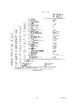
Page 320: ...5 16 Confidential Configuration List ...
Page 337: ...5 33 Confidential EXIT Adjust Check Pattern 1 ...
Page 338: ...5 34 Confidential EXIT Adjust Check Pattern 2 ...
Page 339: ...5 35 Confidential EXIT Adjust Check Pattern 3 ...
Page 340: ...5 36 Confidential KEISEN2 LF300 EXIT ADJUST PATTERN ...
Page 346: ...5 42 Confidential Vertical Alignment Check Pattern ...
Page 349: ...5 45 Confidential Left Right and Bottom Margin Check Pattern ...
Page 383: ...6 4 Confidential Power supply PCB 100 V series ...
Page 384: ...6 5 Confidential Power supply PCB 200 V series ...
Page 385: ...6 6 Confidential Wiring diagrams ...


