


3-113
Confidential
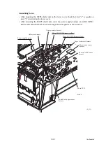
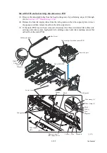
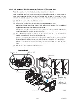
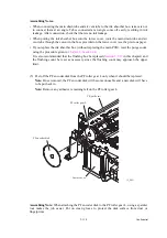
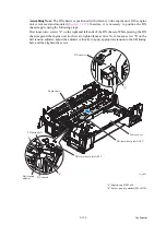
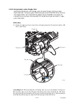
3.9.15 Ink Absorber Box, Ink Absorber Felt, and PF Encoder Disk
Note:
Do not remove the ink absorber box unless it needs to be replaced.
Note:
If the main drain tube and air vent tube are disconnected from the ink absorber box for
replacement of the ink absorber box, they are reusable only one time by trimming their ends
vertically 10 mm with scissors clear and free of oil. Check that their cut surfaces are free of oil.
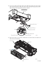
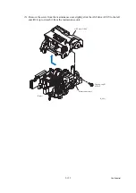
(1) Take the ink absorber box out of the lower cover.
(2) Pull out the main drain tube and air vent tube from the ink absorber box.
Note:
Pinch the end of each tube with a clip in order to prevent drained ink from leaking
and the machine from getting stained with leaked ink.
Note:
Do not place those tubes that have been pulled out on the main PCB. If the PCB is
stained with leaked ink, wipe it off with a dry cloth.
(3) If it is the first time for those tubes to be disconnected, trim their ends to make them
reusable and connect them to a new ink absorber box.
If it is the second time, those tubes need to be replaced. Pull them off the joints on the rear
of the maintenance unit and connect new tubes to the joints and a new ink absorber box.
Note:
If the ink absorber box or its surroundings are stained with ink, wipe them off with a
cloth.
(4) Take the ink absorber felt out of the lower cover.
(3_082)
Viewed from the right
ASF drive ASSY
Main drain tube
Maintenance unit
Ink absorber
box
Ink absorber
felt
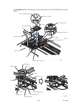
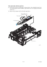
Main drain tube
Correct
Wrong
Do not connect the
main drain tube at
an angle.
Connect the tube
all the way seated.
Lower cover
Cutout in the boss
(for routing the tubes)
Summary of Contents for MFC-J6510DW
Page 15: ...xii Confidential ...
Page 16: ...xiii Confidential ...
Page 17: ...xiv Confidential ...
Page 18: ...xv Confidential ...
Page 19: ...xvi Confidential ...
Page 128: ...3 3 Confidential 3 2 PACKING For models with paper tray 2 ...
Page 273: ...4 13 Confidential EXIT Adjust Check Pattern 1 ...
Page 274: ...4 14 Confidential EXIT Adjust Check Pattern 2 ...
Page 275: ...4 15 Confidential EXIT Adjust Check Pattern 3 ...
Page 276: ...4 16 Confidential KEISEN2 LF300 EXIT ADJUST PATTERN ...
Page 278: ...4 18 Confidential KEISEN GAP EXIT ADJUST PATTERN Line 1 Line 2 Line 3 ...
Page 280: ...4 20 Confidential Vertical Alignment Check Patterns ...
Page 283: ...4 23 Confidential Left Right and Bottom Margin Check Pattern ...
Page 286: ...4 26 Confidential Print Pattern for Creating Head Calibration Data ...
Page 302: ...4 42 Confidential ADF Copy Chart C A B D ...
Page 312: ...5 8 Confidential Print Pattern for Creating Head Calibration Data ...
Page 314: ...5 10 Confidential Scanning Compensation Data List ...
Page 317: ...5 13 Confidential Nozzle Test Pattern ...
Page 320: ...5 16 Confidential Configuration List ...
Page 337: ...5 33 Confidential EXIT Adjust Check Pattern 1 ...
Page 338: ...5 34 Confidential EXIT Adjust Check Pattern 2 ...
Page 339: ...5 35 Confidential EXIT Adjust Check Pattern 3 ...
Page 340: ...5 36 Confidential KEISEN2 LF300 EXIT ADJUST PATTERN ...
Page 346: ...5 42 Confidential Vertical Alignment Check Pattern ...
Page 349: ...5 45 Confidential Left Right and Bottom Margin Check Pattern ...
Page 383: ...6 4 Confidential Power supply PCB 100 V series ...
Page 384: ...6 5 Confidential Power supply PCB 200 V series ...
Page 385: ...6 6 Confidential Wiring diagrams ...


