


3-93
Confidential
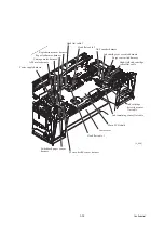
3.9.10 Main PCB
Caution: Before replacement of the main PCB, back up the machine information and user
setting information (refer to
Chapter 5, Section 5.1.4.11 "Backup of Machine Information
(Function code 46) (User-accessible)"
and the head calibration data (refer to
After replacement, restore the backed up
information to the new PCB. Failure to do so requires replacing also the ink absorber box
and flushing box after replacement of the main PCB.
Caution:
Before accessing the main PCB, make sure that the power cord is unplugged from the
electrical outlet and the telephone line is disconnected; otherwise, an electric shock could occur.
Vorsicht:
Bevor Sie auf das Mainboard zugreifen, stellen Sie sicher, dass der Netzstecker aus
der Netzsteckdose gezogen und das Telefonkabel entfernt ist. Andernfalls kann es zu einem
Stromschlag kommen.
Caution:
At the time of removal of the main PCB, untightening screws should be preceded by
disconnection of the harnesses and flat cables, and at the time of installation, connection of the
harnesses and flat cables, by tightening of screws. Observing this sequence prevents harnesses
and flat cables from getting crushed or damaged by screws or screwdrivers.
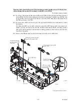
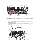
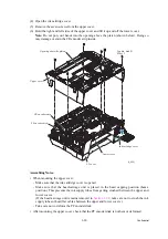
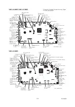
(1) Disconnect the following harnesses and flat cables from the main PCB.
Caution:
Do not remove the screws from the main PCB before disconnecting harnesses
and flat cables.
Note:
After disconnecting the flat cables, check that each cable is not damaged at its end or
short-circuited. When connecting the flat cables, do not insert them at an angle. After
insertion, check again that they are not at an angle.
- Ink cartridge detection sensor flat cable (8-wire)
- High-yield ink cartridge sensor flat cable (7-wire)
- Ink remaining sensor flat cable (9-wire)
- Purge cam switch harness (2-wire)
- Ink cartridge cover switch harness (2-wire)
- ASF* encoder harness (4-wire) (*Auto Sheet Feeder)
- PF encoder/PF sensor harness (7-wire)
- Switchback paper sensor harness (3-wire)
- Registration sensor harness (3-wire)
- Paper feed motor harness (2-wire)
- Power supply harness (6-wire)
- Carriage motor harness (2-wire)
- ASF* motor harness (2-wire)
- Head flat cable 3 (10-wire)
- Head flat cable 2 (12-wire)
- Head flat cable 1 (11-wire)
Summary of Contents for MFC-J6510DW
Page 15: ...xii Confidential ...
Page 16: ...xiii Confidential ...
Page 17: ...xiv Confidential ...
Page 18: ...xv Confidential ...
Page 19: ...xvi Confidential ...
Page 128: ...3 3 Confidential 3 2 PACKING For models with paper tray 2 ...
Page 273: ...4 13 Confidential EXIT Adjust Check Pattern 1 ...
Page 274: ...4 14 Confidential EXIT Adjust Check Pattern 2 ...
Page 275: ...4 15 Confidential EXIT Adjust Check Pattern 3 ...
Page 276: ...4 16 Confidential KEISEN2 LF300 EXIT ADJUST PATTERN ...
Page 278: ...4 18 Confidential KEISEN GAP EXIT ADJUST PATTERN Line 1 Line 2 Line 3 ...
Page 280: ...4 20 Confidential Vertical Alignment Check Patterns ...
Page 283: ...4 23 Confidential Left Right and Bottom Margin Check Pattern ...
Page 286: ...4 26 Confidential Print Pattern for Creating Head Calibration Data ...
Page 302: ...4 42 Confidential ADF Copy Chart C A B D ...
Page 312: ...5 8 Confidential Print Pattern for Creating Head Calibration Data ...
Page 314: ...5 10 Confidential Scanning Compensation Data List ...
Page 317: ...5 13 Confidential Nozzle Test Pattern ...
Page 320: ...5 16 Confidential Configuration List ...
Page 337: ...5 33 Confidential EXIT Adjust Check Pattern 1 ...
Page 338: ...5 34 Confidential EXIT Adjust Check Pattern 2 ...
Page 339: ...5 35 Confidential EXIT Adjust Check Pattern 3 ...
Page 340: ...5 36 Confidential KEISEN2 LF300 EXIT ADJUST PATTERN ...
Page 346: ...5 42 Confidential Vertical Alignment Check Pattern ...
Page 349: ...5 45 Confidential Left Right and Bottom Margin Check Pattern ...
Page 383: ...6 4 Confidential Power supply PCB 100 V series ...
Page 384: ...6 5 Confidential Power supply PCB 200 V series ...
Page 385: ...6 6 Confidential Wiring diagrams ...


