CHAPTER 4 DISASSEMBLY AND RE-ASSEMBLY
4-14
3.5
Access Cover / Battery ASSY
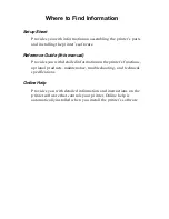
(1) Remove the access cover.
(2) Loosen the two access plate screws.
(3) Remove the access plate.
Fig. 4-22
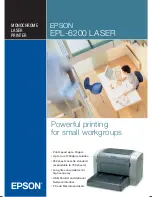
(4) Disconnect the connector of the battery ASSY.
!
CAUTION:
•
There is a danger of explosion if the battery is incorrectly replaced.
•
Use Brother genuine spare part when you replace the battery.
•
Do not disassemble, recharge or dispose of in fire.
•
Used battery should be disposed of according to local regulations.
Fig. 4-23
Access cover
Hooks
Hooks
Hooks
Hooks
Access plate screw
Access plate
screw
Access plate
Main PCB ASSY
Access plate
Battery ASSY
Summary of Contents for MFC-8220
Page 60: ...MFC 8220 SERVICE MANUAL 3 5 1 3 4 ROM Fig 3 6 ...
Page 244: ...CHAPTER 7 MAINTENANCE MODE 7 6 Fig 7 2 a b c d e f g h i j ...
Page 312: ...APPENDIX 4 CIRCUIT DIAGRAM A 48 Appendix 4 1 Main PCB Circuit Diagram 1 6 ...
Page 313: ...MFC 8220 SERVICE MANUAL A 49 Appendix 4 2 Main PCB Circuit Diagram 2 6 ...
Page 314: ...APPENDIX 4 CIRCUIT DIAGRAM A 50 Appendix 4 3 Main PCB Circuit Diagram 3 6 ...
Page 315: ...MFC 8220 SERVICE MANUAL A 51 Appendix 4 4 Main PCB Circuit Diagram 4 6 ...
Page 316: ...APPENDIX 4 CIRCUIT DIAGRAM A 52 Appendix 4 5 Main PCB Circuit Diagram 5 6 ...
Page 317: ...MFC 8220 SERVICE MANUAL A 53 Appendix 4 6 Main PCB Circuit Diagram 6 6 ...
Page 318: ...APPENDIX 4 CIRCUIT DIAGRAM A 54 Appendix 4 7 Engine PCB Circuit Diagram 1 2 ...
Page 319: ...MFC 8220 SERVICE MANUAL A 55 Appendix 4 8 Engine PCB Circuit Diagram 2 2 ...
Page 320: ...APPENDIX 4 CIRCUIT DIAGRAM A 56 Appendix 4 9 NCU PCB Circuit Diagram Europe ...
Page 321: ...MFC 8220 SERVICE MANUAL A 57 Appendix 4 10 NCU PCB Circuit Diagram U S A ...
Page 322: ...APPENDIX 4 CIRCUIT DIAGRAM A 58 Appendix 4 11 Control Panel PCB Circuit Diagram ...
Page 323: ...MFC 8220 SERVICE MANUAL A 59 Appendix 4 12 Low voltage Power Supply PCB Circuit Diagram ...
Page 325: ...MFC 8220 SERVICE MANUAL A 61 Appendix 4 14 High voltage Power Supply PCB Circuit Diagram 200V ...
Page 326: ...APPENDIX 4 CIRCUIT DIAGRAM A 62 Appendix 4 15 Back Light PCB Circuit Diagram ...
Page 328: ...February 04 SM FAX026 6 8X5913 Printed in Japan ...