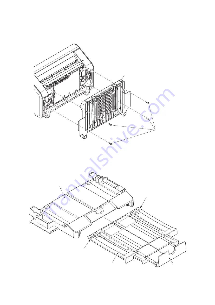
background image

3-14

Confidential

9.2

Bottom cover ASSY / Exit stopper

(1) Remove the four taptite bind B M3x8 screws, and remove the bottom cover ASSY from the machine.

Fig. 3-4

(2) Remove the two stoppers, and remove the exit tray ASSY from the bottom cover ASSY.

(3) Remove the exit stopper from the exit tray ASSY.

Fig. 3-5

Bottom cover ASSY

Taptite bind B 
M3x8

Stopper

Bottom cover ASSY

Stopper

Exit tray ASSY

Exit stopper

Summary of Contents for ImageCenter ADS-2800W

Page 1: ...her Advanced Document Scanner SERVICE MANUAL Read this manual thoroughly before maintenance work Keep this manual in a convenient place for quick and easy reference at all times Nov 2015 SM PT084 2 MODEL ADS 2800W 3600W ...

Page 2: ...tion may be reproduced in any form or by any means without permission in writing from the publisher All other product and company names mentioned in this manual are trademarks or registered trademarks of their respective holders Specifications are subject to change without notice ...

Page 3: ... Adobe and Photoshop are either registered trademarks or trademarks of Adobe Systems Incorporated in the United States and or other countries Each company whose software title is mentioned in this manual has a Software License Agreement specific to its proprietary programs Any trade names and product names of companies appearing on Brother products related documents and any other materials are all...

Page 4: ...ection Drawing 2 3 2 2 Paper Feeding 2 4 2 3 Operation of Each Part 2 5 2 4 Block Diagram 2 6 2 5 Main Components 2 7 3 ERROR INDICATIONS 2 8 3 1 Error Codes 2 8 3 2 Error Messages 2 13 4 TROUBLESHOOTING 2 14 4 1 Error Cause and Remedy 2 14 4 2 Troubleshooting for Image Defects 2 18 4 2 1 Defect examples 2 18 4 2 2 Troubleshooting according to image defect 2 18 4 3 Troubleshooting for Document Pap...

Page 5: ...nsumable part has been replaced 2 28 4 7 7 Installation using USB flash memory is not operable 2 28 CHAPTER 3 DISASSEMBLY REASSEMBLY 1 SAFETY PRECAUTIONS 3 1 2 PACKING 3 2 3 SCREW CATALOGUE 3 3 4 SCREW TORQUE LIST 3 4 5 LUBRICATION 3 5 6 OVERVIEW OF GEARS 3 6 7 HARNESS ROUTING 3 7 8 DISASSEMBLY FLOW CHART 3 10 9 DISASSEMBLY PROCEDURE 3 11 9 1 Reverse roller Pick up roller 3 12 9 2 Bottom cover ASS...

Page 6: ...tting Serial Number 4 6 1 6 Setting Multi Feeding Sensor Threshold 4 7 1 7 Check Sensor Operation 4 8 1 8 Check Multi Feeding Operation 4 8 1 9 Checking Operation after Repair 4 9 1 10 Resetting to Factory Shipping State 4 10 2 IF YOU REPLACE THE CIS UNIT 4 11 2 1 Acquire White Level Data and Set CIS Scan Area 4 11 2 2 Checking Operation after Repair 4 13 3 IF YOU REPLACE THE MULTI FEEDING SENSOR ...

Page 7: ...3 8 Acquire machine log information function code 31 5 10 1 3 9 Check sensor operation function code 32 5 11 1 3 10 Change USB No return value function code 45 5 12 1 3 11 Fine tune scanning position function code 54 5 13 1 3 12 Acquire white level data and set CIS scan area function code 55 5 14 1 3 13 Adjust touch panel function code 61 5 16 1 3 14 Setting by country function code 74 5 17 1 3 15...

Page 8: ...ity Prohibition icons indicate actions that must not be performed Electrical Hazard icons alert you to possible electrical shock Fire Hazard icons alert you to the possibility of fire Unplug icons indicate that you should unplug the machine Note Notes indicates advice about how you should respond to a situation that may arise with your machine and or advice about how the operation of the machine w...

Page 9: ...ular organic solvents or liquids such as benzene paint thinner polish remover or deodorizer may melt or dissolve the plastic cover and or cables resulting in a risk of fire or electric shock These or other chemicals may also cause the machine to malfunction or become discolored The product should be placed so as not to come into contact with any wall or other device Otherwise it could create a ris...

Page 10: ...el and stable surface free from vibration Failure to observe these precautions could cause the machine to fall causing injury to you or others and serious damage to the machine Important DO NOT place your machine next to sources of interference such as speakers or the base units of non Brother cordless telephones Doing so may interfere with the operation of the machine s electronic components DO N...

Page 11: ...om the AC power outlet and contact Brother Authorized Service Personnel Power Cord Safety Use only the power cord supplied with this product DO NOT allow anything to rest on the power cord DO NOT place the machine where people can walk on the cord DO NOT place the machine in a position where the cord is stretched or strain is otherwise put on the cord as it may become worn or frayed DO NOT use the...

Page 12: ...rom lightning when the machine is used during a thunderstorm When disconnecting the AC adapter from the machine or from the power outlet always hold the connector not the cable and pull firmly Failure to do so may result in exposed or broken power cord wires and or create a risk of fire or electric shock Make sure that one end of the power cord is firmly plugged into a standard power outlet and th...

Page 13: ... cloth to clean the unit Do not disassemble or modify the machine otherwise fire or electric shock may result If the machine requires repair contact the place of purchase or Brother Authorized Service Personnel If the machine becomes hot releases smoke or generates any strong or unusual odors immediately unplug the machine from the power outlet and call Brother Customer Service DO NOT handle the p...

Page 14: ...s from being drawn into the machine otherwise an injury may occur In the event that an object is drawn into the machine immediately disconnect the unit from the power source DO NOT swing the AC adapter around or play with it Doing so may result in injury to yourself or others IMPORTANT ADS 2800W ADS 3600W only DO NOT touch the Touchscreen immediately after plugging in the power cord or turning the...

Page 15: ...ork by a qualified technician to restore the machine to normal operation A distinct change in the machine s performance may indicate a need for service ADS 2800W ADS 3600W only DO NOT touch the Touchscreen while the machine is booting up Doing this may cause an error Important safety instructions DO NOT attempt to service the unit yourself because disassembling the unit may expose you to dangerous...

Page 16: ...or 60 ipm 30 ppm 300 dpi 2 0 seconds A4 LTR 100 ipm 50 ppm 300 dpi 1 2 seconds A4 LTR CPU Cortex A9 800 MHz Memory 512 MB Interface USB Hi Speed 2 0 10Base T 100Base TX 1000Base T USB Super Speed 3 0 10Base T 100Base TX 1000Base T Power consumption Scanning Approx 27 W Approx 30 W Ready Approx 3 7 W Approx 4 9 W Sleep Approx 1 9 W Approx 2 9 W Power off Approx 0 12 W Approx 0 12 W Noise level Soun...

Page 17: ...Pentium II or equivalent 150 MB 1 GB Windows Vista 2 Intel Pentium 4 or equivalent 64 bit Intel 64 or AMD 64 supported CPU 500 MB Windows 7 2 650 MB Windows 8 Windows 8 1 Windows Server 2003 only 32 bit Windows Server 2008 Windows Server 2008 R2 Windows Server 2012 Windows Server 2012 R2 3 Macintosh Operating System OS X v10 8 5 Intel Processor 80 MB 1 GB OS X v10 9 x OS X v10 10 x 1 Third party U...

Page 18: ...FAST PEAP EAP TLS EAP TTLS Kerberos IPsec Wireless network Network node type NC 05w Network type IEEE802 11 b g n Infrastructure Mode Ad hoc Mode IEEE802 11 g Wi Fi DirectTM Network security SMTP AUTH SSL TLS HTTPS SMTP SNMP v3 802 1x LEAP EAP FAST PEAP EAP TLS EAP TTLS Kerberos IPsec Part Approximate Life pages Machine life 500 000 sheets A4 LTR MTBF 4 000 hours MTTR 0 5 hours Maximum monthly vol...

Page 19: ...e Part All Models ADF Input 50 sheets ADF Output 50 sheets Duplex Scan Yes Part All Models Paper Input ADF Plain Paper Thin Paper Thick Paper Thicker Paper Recycled Paper Post Card JPN Business Card Plastic Card Media Weight ADF multiple paper 27 to 413 g m2 ADF single paper Plain paper Long paper 27 to 209 g m2 Thick paper 209 to 413 g m2 Media Size ADF multiple paper Width 51 to 215 9 mm Length ...

Page 20: ...1 Windows Vista Windows 7 8 8 1 10 ICA Compliant Macintosh OS X 10 8 x 10 9 x 10 10 x Download only 2 ISISTM Compliant Windows Windows Vista Windows 7 8 8 1 10 Color Depth Input 30 bit color Processing Output 24 bit color Processing Resolution Interpolated Up to 1200 x 1200 dpi Optical Up to 600 x 600 dpi Scanning Width Up to 215 mm Gray Scale 256 levels 1 Windows XP in this Service Manual include...

Page 21: ...ng troubleshooting 1 Be sure to unplug the AC power cord before removing any covers or PCBs adjusting the machine or conducting continuity tests using a tester 2 Do not hold the cable when connecting or disconnecting the cable Be sure to hold the connector 3 Static electricity charged in your body may damage electronic parts Before handling the PCBs touch a metal section of the machine to discharg...

Page 22: ...ended paper is used for the document Refer to 5 2 Media Specifications in Chapter 1 2 The document is not damp 3 Acid paper is not used Others 1 Condensation When the machine is moved to a warm room from a cold location condensation may occur inside the machine causing various problems as listed below Condensation on the surface of optical devices such as the CIS glass and CIS unit may result in p...

Page 23: ...ect jam actuator Duplex scanning speed 100 ipm model only Output tray Eject roller Document tray Multi feeding sensor Receive Pick up roller Paper feed jam actuator Duplex scanning speed 100 ipm model only Feed roller First side CIS unit Multi feeding sensor Sent Reverse roller Document stopper Document detection actuator ...

Page 24: ...2 4 Confidential 2 2 Paper Feeding Fig 2 2 Feed path Front side Back side ...

Page 25: ...r Document detection sensor Detects the document in the document tray Detects document jams Document scanning position actuator Document scanning position sensor Detects document jams Determines whether the document is fed from the document tray Detects document pass and adjusts the scanning start position for the document Paper feed jam actuator Paper feed jam sensor Detects document jams in the ...

Page 26: ... Sent Multi feeding sensor PCB ASSY Receive Document detection sensor PCB Document scanning position sensor PCB Paper feed jam sensor PCB eject jam sensor PCB Panel unit Front cover sensor USB host PCB Wireless LAN PCB Duplex Scanning Speed100 ipm model only Duplex Scanning Speed100 ipm model only DC jack LAN USB3 0 USB2 0 Duplex Scanning Speed 100 ipm model Duplex Scanning Speed 60 ipm model ...

Page 27: ... cover ASSY Exit stopper Paper feed motor USB host PCB ASSY Wireless LAN PCB ASSY Feed motor Multi feeding sensor PCB ASSY Receive Document scanning position sensor PCB Side cover L Feed belt Front cover L Front cover sensor First side CIS unit NFC PCB ASSY Second side CIS unit Pick up roller Multi feeding sensor PCB ASSY Sent Paper feed jam sensor Eject jam sensor Front cover ASSY ...

Page 28: ...ccur during normal use The possible causes are noise around the installation site fluctuation of the power supply voltage and failures in the software Error codes Problem Refer to Error codes Problem Refer to 0101 0D04 0102 0E00 0201 1003 0202 1004 0203 1100 0300 1200 0305 1300 0401 1400 0402 1701 0405 1801 0501 1802 0502 1803 0503 1808 0504 1901 0505 1A01 0506 1B01 0508 1C00 050A 1D01 050B 1D02 0...

Page 29: ...202 4300 6203 4400 6204 4500 6208 4600 6209 4700 620A 4800 6300 4900 6400 4A00 6801 4B01 6901 4B02 6902 4B03 6A00 4B04 6B01 4C01 6B02 4C02 6B03 4C03 6B04 4C04 6B0A 4C05 6C01 4D01 6C02 4E01 6C03 4F01 6C04 4F02 6D00 4F03 6E00 4F04 6F00 5001 7000 5002 7100 5003 7200 5004 7300 5005 7301 5006 7302 6001 7400 6004 7401 6007 7402 6101 7500 ...

Page 30: ...7B02 8A01 7B03 8A02 7B04 8B01 7B05 8C00 7C00 8D01 7D00 8D02 7E00 8E01 8100 A document longer than the specified length was set and scanned 2 14 8E02 8401 8F01 8402 8F02 8403 8F03 8501 9001 8502 9002 8503 9003 8504 9004 8505 9005 8506 9201 8507 9202 8508 9203 8701 9204 8702 9205 8703 9206 8708 9301 8709 9302 870A 9303 870B 9304 870C 9305 870D 9306 870E 9309 870F 930A ...

Page 31: ...scanning position sensor detected that the document length was 90 cm or more while scanning a document 2 14 C900 A300 The document scanning position sensor has not detected the document passing even after the document has been fed for the specified time 2 14 CA00 A400 The front cover sensor detected an open front cover 2 15 D100 A500 D200 A600 D800 An error occurred while initializing the touch pa...

Page 32: ... 2 17 E500 An error occurred during access to the DRAM in the main PCB ASSY 2 17 EC00 An USB device not within the specifications is connected to the USB terminal resulting in overcurrent 2 17 E600 Write error in the EEPROM of the main PCB ASSY 2 17 ED00 E701 EE00 E702 F900 The country code was not entered correctly 2 17 ...

Page 33: ...gth Send or save the scanned image 8100 2 14 Scan Unable Scanning related error Refer to error code Scanner Error Detected that the first side CIS flat cable or second side CIS flat cable was not inserted correctly B000 2 16 A white level not within the standard was scanned when function code 55 was executed BB00 2 16 A black level not within the standard was scanned when function code 55 was exec...

Page 34: ...k Set the document length within the standard Remove the jammed document Step Cause Remedy 1 First side document scanning position actuator caught in sections of the machine Reattach the first side document scanning position actuator 2 First side document scanning position sensor failure Replace the first side document scanning position sensor PCB 3 Main PCB failure Replace the main PCB ASSY User ...

Page 35: ...CB failure Replace the main PCB ASSY Step Cause Remedy 1 Program malfunction Install the latest version of the firmware Refer to 1 1 in Chapter 4 2 First side or second side CIS unit failure Replace the first side or second side CIS unit 3 Main PCB failure Replace the main PCB ASSY User Check Check that the thickness of the document is within the standard Check that the number of documents set in ...

Page 36: ...ond side CIS unit flat cable 3 First side or second side CIS unit failure Replace the first side or second side CIS unit 4 Main PCB failure Replace the main PCB ASSY Step Cause Remedy 1 Dirty calibration sheet Replace the calibration sheet with a new one 2 First side or second side CIS unit failure Replace the first side or second side CIS unit 3 Main PCB failure Replace the main PCB ASSY User Che...

Page 37: ...failure of the panel PCB flat cable Reconnect the panel PCB flat cable 2 Panel PCB failure Replace the panel PCB ASSY 3 NFC PCB failure Replace the NFC PCB ASSY 4 Main PCB failure Replace the main PCB ASSY User Check Disconnect the USB device from the USB terminal and turn the machine OFF Turn the machine ON again after a while Replace the USB device with a different one Step Cause Remedy 1 USB ho...

Page 38: ...on data Execute the maintenance mode function Acquire white level data and set CIS scan area Refer to 1 3 12 in Chapter 5 2 Dirty calibration sheet Replace the calibration sheet with a new one 3 First side or second side CIS unit failure Replace the first side or second side CIS unit 4 Main PCB failure Replace the main PCB ASSY Light White vertical streaks Vertical streaks Completely blank Hue def...

Page 39: ...hapter 5 2 Dirty calibration sheet Replace the calibration sheet with a new one 3 First side or second side CIS unit failure Replace the first side or second side CIS unit 4 Main PCB failure Replace the main PCB ASSY User Check Check that the document is not reversed Check that the document is set in the document tray correctly Step Cause Remedy 1 Incorrect white level correction data Execute the ...

Page 40: ...an the feeding path Step Cause Remedy 1 First side or second side CIS unit failure Replace the first side or second side CIS unit User Check Clean the document glass or CIS glass Step Cause Remedy 1 Color parameter failure Execute the maintenance mode function Acquire white level data and set CIS scan area Refer to 1 3 12 in Chapter 5 2 Dirty calibration sheet Replace the calibration sheet with a ...

Page 41: ...he first side or second side CIS unit 4 Main PCB failure Replace the main PCB ASSY User Check Clean the feeding path Moisten a soft cloth with cleaning solution Gently and evenly wipe the pick up roller and reverse roller perpendicular to the direction of the rotation with the cloth to clean it Note Do not use any solution except the one packaged in the accessory ethanol or detergent on the market...

Page 42: ...or PCB harness Reconnect the document detection sensor PCB harness 6 Attachment failure of the gears in a feeding system Reattach the gears in a feeding system 7 Front cover sensor failure Replace the front cover sensor 8 Document detection sensor failure Replace the document detection sensor PCB 9 Feed motor failure Replace a feed motor ASSY 10 Main PCB failure Replace the main PCB ASSY User Chec...

Page 43: ...k that the front cover is closed correctly Step Cause Remedy 1 Foreign object inside the front cover Remove the foreign object inside the front cover 2 Document scanning position actuator coming off Reattach the document scanning position actuator 3 Document pinch roller coming off Reattach the document pinch roller 4 Connection failure of the document scanning position sensor PCB harness Reconnec...

Page 44: ... 1 Program malfunction Install the latest version firmware Refer to 1 1 in Chapter 4 2 Connection failure of the front cover sensor harness Reconnect the front cover sensor harness 3 Front cover sensor failure Replace the front cover sensor ASSY 4 Main PCB failure Replace the main PCB ASSY User Check Check that the USB cable or LAN cable is not damaged When using an interface switch check that the...

Page 45: ...lure Replace the AC adapter 5 Panel PCB failure Replace the panel PCB ASSY 6 Key PCB failure Replace the panel unit 7 Main PCB failure Replace the main PCB ASSY User Check Check that the function lock is not set Step Cause Remedy 1 Connection failure of the key PCB harness Reconnect the key PCB harness 2 Connection failure of the panel PCB harness Reconnect the panel PCB harness 3 Connection failu...

Page 46: ...AN cable Step Cause Remedy 1 Connection failure of the wireless LAN PCB connector Reconnect the wireless LAN PCB ASSY connector 2 Wireless LAN PCB failure Replace the wireless LAN PCB ASSY 3 Deformed LAN terminal pin Main PCB failure Replace the main PCB ASSY User Check Check the wireless LAN settings Check the access point settings Change the machine installation location Set the access point man...

Page 47: ...mware version does not match Install the latest version firmware Refer to 1 1 in Chapter 4 2 Main PCB failure Replace the main PCB ASSY User Check Check that the USB flash memory is inserted into the USB terminal correctly Replace the USB flash memory and try saving data again Check that the USB flash memory is not write protected Step Cause Remedy 1 Connection failure of the USB host PCB harness ...

Page 48: ... USB flash memory Create the FIRM folder under the USB flash memory 2 _ UPD OP0 8080 file for automatic firmware update cannot be found under the USB flash memory Save the _ UPD OP0 8080 file for automatic firmware update under the USB flash memory 3 Firmware djf file cannot be found in the FIRM folder Save the firmware djf file in the FIRM folder 4 There is an unnecessary file in the FIRM folder ...

Page 49: ...eets When replacing the PCB and all the other related parts put on a grounding wrist band and perform the job on a static mat Also take care not to touch the conductor sections on the flat cables or on the wire harnesses After disconnecting flat cables check that each cable is not damaged at its end or short circuited When connecting flat cables do not insert them at an angle After insertion check...

Page 50: ...3 2 Confidential 2 PACKING ...

Page 51: ...3 3 Confidential 3 SCREW CATALOGUE Taptite bind B Taptite cup B Taptite bind B M4x10 Taptite bind B M3x8 Taptite cup B M3x10 Screw bind Screw cup Screw cup M3x6 Screw bind M3x6 Taptite cup B M2 6x10 BK ...

Page 52: ... 1 5 1 FG harness YW 1 FG harness FG spring A Screw cup M3x6 1 0 7 0 1 7 1 FG spring B Screw cup M3x6 1 0 7 0 1 7 1 EJ pinch roller support plate Taptite bind B M3x8 2 0 5 0 1 5 1 Sensor holder C Taptite bind B M3x8 1 0 5 0 1 5 1 Reverse roller holder support Screw cup M3x6 2 0 7 0 1 7 1 Pinch roller support Taptite bind B M3x8 1 0 5 0 1 5 1 FG spring Screw cup M3x6 1 0 7 0 1 7 1 Document scanning...

Page 53: ...3 5 Confidential 5 LUBRICATION There are no applicable parts for lubrication ...

Page 54: ...3 6 Confidential 6 OVERVIEW OF GEARS There are no gears to be disassembled ...

Page 55: ...e Front cover sensor harness WH Multi feeding sensor harness Sent WH BK Paper feed Eject jam sensor harness BL RD FG harness YW FG harness GR Feed motor harness RD Paper feed motor harness BK Panel flat cable First side CIS flat cable Document detection Document scanning position sensor harness GR WH Multi feeding sensor harness Receive RD BK WH BL ...

Page 56: ... side of the machine Harness colors are subject to change for some reason Front cover sensor harness WH Feed motor harness RD Paper feed motor harness BK Paper feed motor harness BK Feed motor harness RD Multi feeding sensor harness Receive RD BK WH BL ...

Page 57: ...lat cable Key PCB flat cable NFC flat cable FG harness YW FG harness GR Paper feed jam sensor harness RD Eject jam sensor harness BL Second side CIS flat cable Multi feeding sensor harness Sent WH BK Document detection sensor harness GR Document scanning position sensor harness WH Panel flat cable ...

Page 58: ...20 20 9 17 Front cover sensor 10 15 9 10 Panel unit 40 50 9 5 Wireless LAN PCB ASSY 5 5 9 11 Flat cable support film 5 5 9 14 Paper feed jam sensor PCB Multi feeding sensor PCB ASSY Sent 60 90 9 11 Second side CIS flat cable 15 40 9 10 LCD presser base 25 50 9 10 LCD 5 5 9 10 Panel PCB ASSY 5 5 9 10 Touch panel 5 10 9 12 Eject jam sensor PCB 5 10 9 20 Multi feeding sensor PCB ASSY Receive 35 45 9 ...

Page 59: ... to proceeding with the disassembly procedure 1 Disconnect the following AC adapter AC power cord USB cable if connected LAN cable if connected USB flash memory if connected 2 Remove the following Document tray LAN port cap Fig 3 1 USB cable AC adapter LAN cable LAN port cap USB flash memory Document tray ...

Page 60: ...oller 1 Push the release button and open the front cover ASSY 2 Open the reverse roller cover to remove the reverse roller from the machine Fig 3 2 3 Close the reverse roller cover Reverse roller Release button Front cover ASSY Reverse roller cover ...

Page 61: ... Fig 3 3 6 Close the pick up roller cover and then the front cover ASSY Assembling Note When attaching the pick up roller make sure that the lever hook is engaged with the groove on the machine If not the pick up roller wears out quickly because it comes in contact with the pick up roller cover Pick up roller Pick up roller cover Lever A Groove Lever hook ...

Page 62: ... and remove the bottom cover ASSY from the machine Fig 3 4 2 Remove the two stoppers and remove the exit tray ASSY from the bottom cover ASSY 3 Remove the exit stopper from the exit tray ASSY Fig 3 5 Bottom cover ASSY Taptite bind B M3x8 Stopper Bottom cover ASSY Stopper Exit tray ASSY Exit stopper ...

Page 63: ...r 1 Push the release button and open the front cover ASSY 2 Open the pick up roller cover to remove the two taptite cup B M3x10 screws from the machine Fig 3 6 Pick up roller cover Taptite cup B M3x10 Front cover ASSY Release button ...

Page 64: ...3 16 Confidential 3 Release the four hooks to remove the back cover from the machine in the direction of the arrow Fig 3 7 4 Close the pick up roller cover Hooks Hooks Back cover ...

Page 65: ...3 17 Confidential 9 4 Side cover L R 1 Release the three hooks and remove the side cover L from the machine Fig 3 8 Hooks Hook Side cover L ...

Page 66: ...3 18 Confidential 2 Release the three hooks and remove the side cover R from the machine Fig 3 9 3 Close the front cover ASSY Hook Side cover R Hooks ...

Page 67: ...3 19 Confidential 9 5 Wireless LAN PCB ASSY 1 Remove the wireless LAN PCB ASSY from the main PCB ASSY Fig 3 10 Wireless LAN PCB ASSY Main PCB ASSY ...

Page 68: ... 2 Remove the three taptite cup B M3x10 screws and remove the USB host FG plate from the machine 3 Remove the USB host PCB ASSY from the machine Fig 3 11 HARNESS ROUTING Refer to 1 Main PCB ASSY Taptite cup B M3x10 USB host FG plate Taptite cup B M3x10 USB host PCB ASSY USB host PCB harness Second side CIS flat cable Main PCB ASSY ...

Page 69: ...onnected to the main PCB ASSY Fig 3 13 HARNESS ROUTING Refer to 1 Main PCB ASSY Main PCB upper shield Copper seal Main PCB ASSY First side CIS flat cable Panel flat cable Feed motor harness Paper feed motor harness Multi feeding sensor harness Sent Multi feeding sensor harness Receive Front coversensor harness Document detection Document scanning position sensor harness Paper feed Eject jam sensor...

Page 70: ...Fig 3 14 4 Remove the three taptite cup B M3x10 screws to remove the FG harness YW FG harness GR and main PCB upper lower shield from the machine Fig 3 15 HARNESS ROUTING Refer to 1 Main PCB ASSY Taptite bind B M3x8 Drive earth plate Taptite cup B M3x10 Main PCB upper lower shield FG harness YW FG harness GR ...

Page 71: ...16 Fig 3 17 Assembling Note When assembling the main PCB upper shield insert the two ribs of the main PCB upper shield below the main PCB lower shield When opening the main PCB upper shield take care not to break the copper seal If the copper seal is broken replace it with a new one Ribs Screw cup M3x6 Main PCB lower shield Main PCB upper shield Copper seal Ribs Main PCB lower shield Copper seal 3...

Page 72: ...emove the heat conductive sheet B and heat conductive sheet A from the main PCB ASSY Fig 3 19 Assembling Note Attach the heat conductive sheet A and heat conductive sheet B in the red frame described in the figure above Screw cup M3x6 Main PCB ASSY Main PCB lower shield Heat conductive sheet B Heat conductive sheet A Main PCB ASSY ...

Page 73: ...ribs of the main PCB upper shield below the main PCB lower shield When assembling the main PCB upper shield make sure to check that the main PCB upper shield is in contact with the radio wave absorptive sheet properly as shown in the figure above Main PCB upper shield Main PCB upper shield Main PCB upper shield Screw cup M3x6 Ribs Ribs Main PCB lower shield Main PCB lower shield Radio wave absorpt...

Page 74: ...ws and remove the main PCB ASSY from the machine Fig 3 22 Main PCB ASSY First side CIS flat cable Panel flat cable Feed motor harness Paper feed motor harness Multi feeding sensor harness Sent Multi feeding sensor harness Receive Front coversensor harness Document detection Document scanning position sensor harness Paper feed Eject jam sensor harness Screw cup M3x6 Main PCB ASSY ...

Page 75: ...et B and heat conductive sheet A from the main PCB ASSY Fig 3 23 Assembling Note Attach the heat conductive sheet A and heat conductive sheet B in the red frame described in the figure above Heat conductive sheet B Heat conductive sheet A Main PCB ASSY ...

Page 76: ... 1 Release the hook of the front cover L and remove the front cover L from the machine Fig 3 24 Assembling Note When assembling the front cover L engage the slit of the front cover L with the rib of the machine Slit Front cover L Rib Hook ...

Page 77: ... the hook of the front cover R and remove the front cover R from the machine Fig 3 25 Assembling Note When assembling the front cover R engage the slit of the front cover R with the rib of the machine Slit Front cover R Rib Hook ...

Page 78: ...Release all the panel unit harnesses from the securing fixtures 2 Push the release button and open the front cover ASSY 3 Remove the two bosses and remove the front cover ASSY from the machine Fig 3 26 Boss Front cover ASSY Boss Release button ...

Page 79: ...ptite cup B M2 6x10 BK screws 2 Release the four tabs to lift the front cover ASSY Slide the panel unit in the direction of the arrow to release the four hooks and remove the panel unit from the front cover ASSY Fig 3 27 Taptite cup B M2 6x10 BK Tabs Front cover ASSY Hooks Hooks Panel unit Taptite cup B M2 6x10 BK ...

Page 80: ...base from the panel unit Fig 3 28 HARNESS ROUTING Refer to 4 Panel unit Fig 3 29 Assembling Note When connecting the key PCB flat cable fold it as shown in the figure below Taptite cup B M3x10 Taptite cup B M3x10 Key PCB flat cable Hooks Hook LCD presser base Panel unit Panel PCB ASSY Mountain fold Key PCB flat cable 45 Panel PCB side Reinforcing plate 33 Key PCB ASSY Mountain fold at the end of r...

Page 81: ...panel PCB ASSY Remove the LCD 6 Disconnect the touch panel flat cable from the key PCB ASSY 7 Remove the taptite cup B M3x10 screw to remove the touch panel unit Fig 3 30 Panel PCB ASSY Taptite cup B M3x10 LCD LCD flat cable Touch panel unit Touch panel flat cable Lock Key PCB ASSY ...

Page 82: ... PCB ASSY and panel insulation sheet panel shield plate base from the panel unit Fig 3 31 HARNESS ROUTING Refer to 4 Panel unit Fig 3 32 Assembling Note When connecting the panel flat cable fold it as shown in the figure below Panel unit NFC flat cable Panel shield plate top Panel insulation sheet panel shield plate base Panel PCB ASSY Panel flat cable FG harness YW Taptite cup B M3x10 Mountain fo...

Page 83: ...Fig 3 33 Fig 3 34 Assembling Note When connecting the NFC flat cable fold it as shown in the figure below Panel unit NFC PCB ASSY Hook NFC flat cable 29 NFC PCB 8 2 45 45 Reinforcing plate Panel PCB side Mountain fold at the end of reinforcing plate 11 27 38 2 Mountain fold Valley fold ...

Page 84: ...two ribs outwards to remove the second side CIS unit from the front cover ASSY Disconnect the second side CIS flat cable from the second side CIS unit 2 Remove the second side CIS spring from the machine Fig 3 35 Second side CIS unit Rib Second side CIS flat cable Rib Second side CIS spring Front cover ASSY ...

Page 85: ...ve force once it is removed Replace it with a new one Assembling Note When securing the flat cable support film with the double sided tapes attach the tape on the position shown in the figure above When connecting the second side CIS flat cable fold it as shown in the figure below Second side CIS flat cable Flat cable support film Front cover ASSY Double sided tapes Second side CIS flat cable 31 4...

Page 86: ...two taptite bind B M3x8 screws and remove the EJ pinch roller support plate spring C and two springs D from the front cover ASSY 4 Remove the taptite bind B M3x8 screw and remove the sensor holder C from the front cover ASSY Fig 3 38 HARNESS ROUTING Refer to 4 Panel unit Screw cup M3 6 FG spring B Eject jam sensor PCB Taptite bind B M3x8 Sensor holder C Taptite bind B M3x8 EJ pinch roller support ...

Page 87: ...s Remove the FG spring and reverse roller holder support from the front cover ASSY Remove the two springs Fig 3 39 Assembling Note Guide film should not be reused as its double sided tape looses the adhesive force once it is removed Replace it with a new one Guide film Screw cup M3x6 Springs FG spring Reverse roller holder support Front cover ASSY ...

Page 88: ...rom the rib and remove it from the front cover ASSY in the direction of the arrow b Remove the spring A and two springs B Fig 3 40 Assembling Note When assembling the pinch roller support insert the pinch roller support below the rib as shown in the figure below Pinch roller support Spring B Spring A Spring B Taptite bind B M3x8 Screw cup M3x6 FG spring Front cover ASSY Ribs a b ...

Page 89: ...ove the document scanning position sensor PCB from the front cover ASSY 5 Disconnect the document scanning position sensor harness from the document scanning position sensor PCB Fig 3 41 HARNESS ROUTING Refer to 4 Panel unit Document scanning position sensor harness Document scanning position sensor PCB Front cover ASSY Hook ...

Page 90: ...sensor PCB Multi feeding sensor PCB ASSY Sent 1 Release the hook to remove the paper feed jam sensor PCB from the document scanning position actuator holder Fig 3 42 Document scanning position actuator holder Hook Paper feed jam sensor PCB ...

Page 91: ... ASSY 3 Release the multi feeding sensor harness from the securing fixtures and remove the multi feeding sensor PCB ASSY Sent from the front cover ASSY Fig 3 43 HARNESS ROUTING Refer to 4 Panel unit Taptite bind B M3x8 Document scanning position actuator holder Front cover ASSY Multi feeding sensor PCB ASSY Sent Multi feeding sensor harness ...

Page 92: ...over ASSY 2 Release the document detection sensor harness from the securing fixtures Release the hook to remove the document detection sensor PCB ASSY from the front cover ASSY Fig 3 44 HARNESS ROUTING Refer to 4 Panel unit Taptite bind B M3x8 PF pinch roller holder Front cover ASSY Document detection sensor PCB ASSY Document detection sensor harness Hook ...

Page 93: ...CIS unit First side CIS flat cable 1 Release the hook to remove the first side CIS unit from the machine 2 Disconnect the first side CIS flat cable from the first side CIS unit Fig 3 45 First side CIS unit Hook First side CIS flat cable ...

Page 94: ...t side CIS flat cable Fig 3 46 HARNESS ROUTING Refer to 1 Main PCB ASSY Fig 3 47 Assembling Note When connecting the first side CIS flat cable fold it as shown in the figure below Core Hook First side CIS flat cable 87 64 63 Insulation tape area 45 First side CIS flat cable 88 50 179 Main PCB side CIS side Mountain fold Valley fold ...

Page 95: ...bind B M3x8 screw and remove the front cover sensor holder from the machine 2 Release the two hooks to remove the front cover sensor from the front cover sensor holder Fig 3 48 HARNESS ROUTING Refer to 2 Right side of the machine Front cover sensor Front cover sensor holder Taptite bind B M3x8 Front cover sensor harness Hook Hook ...

Page 96: ...Remove the four taptite cup B M3x10 screws and remove the lower frame from the machine Pull out the multi feeding sensor harness from the hole of the lower frame Fig 3 49 HARNESS ROUTING Refer to 2 Right side of the machine and 3 Rear side of the machine Taptite cup B M3x10 Taptite cup B M3x10 Hole Lower frame Feed motor harness Paper feed motor harness Multi feeding sensor harness ...

Page 97: ... Remove the feed belt 5 Remove the two screw bind M3x6 screws and remove the feed motor from the machine Fig 3 50 Fig 3 51 Assembling Note Hook the feed belt on each gear as shown in the figure below Tension pulley Feed belt Screw cup M3x6 Screw bind M3x6 Feed motor Tension pulley Feed belt Feed motor ...

Page 98: ...ixtures 2 Remove the three taptite bind B M4x10 screws Lift the plate and FG spring then remove the paper feed motor unit from the machine Fig 3 52 HARNESS ROUTING Refer to 2 Right side of the machine and 3 Rear side of the machine Paper feed motor harness Paper feed motor unit Taptite bind B M4x10 Plate FG spring ...

Page 99: ...ove the paper feed belt from the paper feed motor unit 5 Remove the two screw bind M3x6 screws and remove the paper feed motor from the paper feed motor unit Fig 3 53 Paper feed motor unit Paper feed motor Paper feed belt Screw bind M3x6 Screw bind M3x6 Gear Retaining ring E ...

Page 100: ...ti feeding sensor harness guide from the machine 2 Open the multi feeding sensor harness guide and remove it from the multi feeding sensor harness Fig 3 54 HARNESS ROUTING Refer to 3 Rear side of the machine Taptite bind B M3x8 Multi feeding sensor harness Multi feeding sensor harness Multi feeding sensor harness guide ...

Page 101: ...nd B M3x8 screws Lift the plate then remove the multi feeding sensor shield plate and multi feeding sensor PCB ASSY Receive from the machine Fig 3 55 Multi feeding sensor shield plate Taptite bind B M3x8 Multi feeding sensor PCB ASSY Receive Plate ...

Page 102: ... on the C drive 5 Maintenance driver MaintenanceDriver zip When the maintenance driver is not installed on the computer copy this file into the temporary folder created on the C drive and extract the copied file Refer to APPENDIX 3 INSTALLING THE MAINTENANCE PRINTER DRIVER to install 6 Firmware 7 Sheet for multi feeding sensor threshold setting LD6340001 8 Multi feeding sensor threshold setting to...

Page 103: ...d the key for approximately five seconds while the machine is in the ready state 2 Press the blank field at the bottom 3 Press the 2 8 6 and 4 keys on the LCD in this order to enter the maintenance mode 4 Press the 2 and 5 keys in this order The main firmware version information is displayed on the LCD Check the main firmware version 5 Press the Start key a few times to display M The first M is fi...

Page 104: ...tart automatically after the restart If the installation fails Update Fail appears on the LCD indicates the error code Refer to the remedy and eliminate the error Then reboot the machine and start from the procedure 1 Firmware installation using PC 1 Press and hold the key The following screen appears on the LCD Error display Description Remedy Update Fail 0001 Memory full Failed to secure the wor...

Page 105: ... machine and installing to the flash ROM starts 8 Back light of the LCD flashes randomly during the installation When installing is completed the machine restarts and returns to the ready state automatically Do not disconnect the USB cable or turn OFF the power switch of the computer until installing is completed 9 Disconnect the USB cable and unplug the AC power cord of the machine 10 Repeat the ...

Page 106: ...f the specified area was adjusted correctly Then the machine returns to the initial state of maintenance mode 1 3 Setting by Country 1 Check the country code to set in the country code table on page 5 17 2 Press the 7 and then the 4 key in the maintenance mode The country code is displayed on the LCD 3 Enter the country code checked in 1 4 Press the Start key The country code is set and the machin...

Page 107: ...rcled in red If the model name is not displayed click the Find Next button until it appears in the field B circled in red 4 Check that the Brother Maintenance USB Printer is set as a default printer If not set it as a default printer 5 Double click the MemoryAccessTool exe file The following window appears 6 Enter the Y Memory writing is activated 7 In the Port field select the port number assigne...

Page 108: ...multi feeding sensor threshold is set 4 Set the sheet for multi feeding sensor threshold setting in the ADF and execute the maintenance mode function Check ADF Refer to 1 3 2 ADF performance test function code 08 in Chapter 5 5 Execute the maintenance mode function Acquire white level data and set CIS scan area Refer to 1 3 12 Acquire white level data and set CIS scan area function code 55 in Chap...

Page 109: ...play on the LCD changes depending on the sensor status Check sensor function by operating each actuator 4 When all sensors are checked press the key to quit the sensor function check mode 1 8 Check Multi Feeding Operation 1 Check that the machine is in the initial state of maintenance mode 2 Set the document for multi feeding sensor threshold setting in the ADF unit DOC READY is displayed on the L...

Page 110: ...hile the machine is in the ready state 3 Press the blank field at the bottom 4 Press the 2 8 6 and 4 keys on the LCD in this order to enter the maintenance mode 5 Connect the machine to your computer using the USB cable 6 Start the PaperPort 7 Select the Desktop tag and click the Select button 8 Select TW Maintenance USB and click the OK button 9 When the screen shown on the right appears during t...

Page 111: ...ng to Factory Shipping State These procedures are for when the new main PCB ASSY for replenishment is used They are not necessary for when the main PCB ASSY which has been used successfully in the market is used 1 Check that the machine is in the initial state of maintenance mode 2 Turn ON the power switch of the computer 3 Check that the Brother Maintenance USB Printer is set as a default printer...

Page 112: ...e 1 Calibration sheet LD1914001 2 USB flash memory 3 Scan limit sample 4 Test chart DS 001 LD1625001 2 1 Acquire White Level Data and Set CIS Scan Area 1 Wipe the first and second side CIS glass four times in the same direction with a cleaning cloth 2 Press and hold the key The following screen appears on the LCD 3 Press the 4th blank box The following screen appears on the LCD ...

Page 113: ...Once Clear CS and Press Start Key is displayed on the LCD open the front cover and remove the calibration sheet 10 Close the front cover and press the Start key The machine saves the scanning compensation data to EEPROM and returns to the initial state of maintenance mode 11 Wipe the first and second side CIS glass four times in the same direction with a cleaning cloth again Note Keep the calibrat...

Page 114: ...hile the machine is in the ready state 3 Press the blank field at the bottom 4 Press the 2 8 6 and 4 keys on the LCD in this order to enter the maintenance mode 5 Connect the machine to your computer using the USB cable 6 Start the PaperPort 7 Select the Desktop tag and click the Select button 8 Select TW Maintenance USB and click the OK button 9 When the screen shown on the right appears during t...

Page 115: ...ample perform procedures in Acquire white level data and set CIS scan area again And then wipe the first and second side CIS glass with a dry cleaning cloth four times in the same direction and follow the instructions above again to scan If the problem persists replace the CIS Test chart DS 001 Black band bmp Black streak bmp White band bmp White streak bmp OK limit OK limit OK limit OK limit ...

Page 116: ...peration What you need to prepare 1 Sheet for multi feeding sensor threshold setting LD6340001 2 Multi feeding sensor threshold setting tool brADSmt1 exe Copy this file into the temporary folder created on the C drive 3 1 Setting Multi Feeding Sensor Threshold 1 Press and hold the key The following screen appears on the LCD 2 Press the 4th blank box The following screen appears on the LCD ...

Page 117: ...fter the following screen is appeared set the sheet for multi feeding sensor threshold setting in the ADF and execute the maintenance mode function Check ADF Refer to 1 3 2 ADF performance test function code 08 in Chapter 5 7 Execute the maintenance mode function Acquire white level data and set CIS scan area Refer to 1 3 12 Acquire white level data and set CIS scan area function code 55 in Chapte...

Page 118: ...sensor threshold setting in the ADF unit DOC READY is displayed on the LCD 5 Press the 0 and then the 8 key Check that ADF CHECK P 01 is displayed on the LCD and the machine ejects the document properly 6 When the document is ejected properly press the key to quit the sensor function check mode 7 Press the 9 key twice in the initial state of maintenance mode The machine quits maintenance mode and ...

Page 119: ...ction code 61 Checking LCD operation function code 12 Checking control panel operation function code 13 What you need to prepare 1 Touch panel stylus 4 1 Adjusting Touch Panel 1 Press and hold the key The following screen appears on the LCD 2 Press the 4th blank box The following screen appears on the LCD ...

Page 120: ...t upper right and center When the center 5th mark is touched OK is displayed if the specified area was adjusted correctly The following screen appears consecutively and the machine returns to the initial state of maintenance mode in three seconds 4 2 Checking LCD Operation 1 Press the 1 and then the 2 key in the initial state of maintenance mode The LCD check display appears on the LCD Refer to 1 ...

Page 121: ...LCD 2 Press the keys on the control panel according to the numbers provided on the figure in 1 3 5 Check control panel key operation function code 13 in Chapter 5 3 If the button operation is normal the machine returns to the initial state of maintenance mode when the last key is pressed 4 Press the 9 key twice to return the machine to the ready state ...

Page 122: ...PICK UP ROLLER REVERSE ROLLER What to do after replacement Resetting pick up roller reverse roller counters 5 1 Resetting Pick Up Roller Reverse Roller Counters Refer to the User s Guide to reset the pick up roller or reverse roller counters ...

Page 123: ...tenance mode for service personnel Operating Procedure 1 Press and hold the key for approximately five seconds while the machine is in the ready state The display shown on the right appears on the LCD 2 Press the blank field at the bottom The display shown on the right appears on the LCD 3 Press the 2 8 6 and 4 keys on the LCD in this order The display shown on the right appears on the LCD and the...

Page 124: ...unction code 10 12 18 25 45 54 61 80 82 91 Operating Procedure 1 Press and hold the key for approximately five seconds while the machine is in the ready state The display shown on the right appears on the LCD 2 Press the blank field at the bottom The display shown on the right appears on the LCD 3 Press the 0 and keys on the LCD in this order The machine enters to the ready state to accept functio...

Page 125: ...ck LCD operation 5 7 13 Check control panel key operation 5 8 18 Save NetConfig data 5 8 25 Display software version 5 9 32 Check sensor operation 5 11 45 Change USB No return value 5 12 54 Fine tune scanning position 5 13 55 Acquire white level data and set CIS scan area 5 14 61 Adjust touch panel 5 16 74 Setting by country 5 17 80 Display machine log information 5 18 82 Display machine error cod...

Page 126: ...r in the initial state of maintenance mode to display PARAMETER INIT or press the 9 and 1 keys as appropriate on the LCD 2 When initializing parameters is completed the machine returns to the initial state of maintenance mode Data item Function code 01 Function code 91 Counter information Areas not to be initialized Areas not to be initialized Error history MAC address Worker switches Areas to be ...

Page 127: ...and then the 8 key in the initial state of maintenance mode ADF CHECK P is displayed on the LCD and the documents are ejected while the scanned pages are counted indicates the current count of the scanned pages 3 When the key is pressed the machine returns to the initial state of maintenance mode Note If the front cover is open Close the ADF cover is displayed on the LCD Close the front cover and ...

Page 128: ...e the setting by pressing the 1 or 0 key 4 When changing the setting is completed press the SET key The new selector setting value is stored in the EEPROM and the LCD returns to the ready state for worker switch number entry WSW00 5 When all switch setting is completed press the key to return the machine to the initial state of maintenance mode WSW No Selector Function WSW17 5 Change time display ...

Page 129: ...e below When the key is pressed on display 7 the LCD returns to display 1 3 When the key is pressed the machine returns to the initial state of maintenance mode regardless of the display status Complete red Complete green Complete blue Complete gray Display B 1 Gradation red Display B 2 Gradation green Display B 3 Gradation blue Display B 4 Stroke detection screen Display B 5 Display B 6 Display B...

Page 130: ...rrect key 3 If the key operation is normal the machine returns to the initial state of maintenance mode when the last key is pressed To cancel the operation and return to the initial state of maintenance mode press the key Order of pressing keys 1 3 6 Save NetConfig data function code 18 Function This function is used to save NetConfig data to the USB flash memory Operating Procedure 1 Press the 1...

Page 131: ...cks if these two types of check sum information match each other When the OK or SET key is pressed while ROM Check Sum is displayed check is automatically conducted for each ROM of each software part When the check sum matches OK is displayed on the LCD When all ROMs result in OK ROM Check Sum OK is displayed at the end and the operation is finished When the check sum of any ROM does not match NG ...

Page 132: ...5 12 00 the file name is BRSUPPLY_ E75166M5G123456_1512311200 Maintenance information 1 Model code 14 Total pages scanned 2 Model name 15 Total pages of single side scanning 3 Model code Country code 16 Total pages of duplex scanning 4 Main firmware version 17 Total pages scanned 5 Serial number 18 Total paper jams 6 Main PCB serial number 19 Total paper jams of single side scanning 7 ADF unit ser...

Page 133: ...en the top front cover 3 When the key is pressed this operation is finished and the machine returns to the initial state of maintenance mode The table below summarizes the displays on the LCD sensor names and detection status Location of sensors LCD Sensor name Detection status displayed not displayed AC Front cover sensor Front cover closed Front cover open DF Document detection sensor Document s...

Page 134: ... No return value to 0 The setting currently selected is marked with at the end of the display Operating Procedure 1 Press the 4 and then the 5 key in the initial state of maintenance mode USBNo is displayed on the LCD 2 Press the SET key USBNo ON is displayed on the LCD 3 Press the or key to select USBNo OFF when fixing the serial number return value to 0 or USBNo ON when not fixing it and press t...

Page 135: ...anning press the key 3 FRONT BACK is displayed on the LCD Press key to adjust the first side Press key to adjust the second side 4 Press the key to adjust the compensation level in the positive direction or press the key to adjust it in the negative direction Compensation levels for sub scanning can be adjusted in 41 levels from 20 to 20 Compensation levels for main scanning can be adjusted in 41 ...

Page 136: ... compensation data to EEPROM and returns to the initial state of maintenance mode 8 Wipe the first and second side CIS glass four times in the same direction with a cleaning cloth again 9 Turn OFF the power of the machine to finish it Note If any error occurs on this operation press the Stop key and return the machine to the initial state of maintenance mode Then refer to the table below and start...

Page 137: ...e CIS or gray tape detected that the data acquired on the gray tape of the second side CIS was out of normal range Clean the second side CIS unit Or replace the second side CIS GT ERR L Dirt on the first side CIS or gray tape detected that the data acquired on the gray tape of the first side CIS was out of normal range Clean the first side CIS unit Or replace the first side CIS GT ERR UL Dirt on t...

Page 138: ...te This adjustment requires a touch panel stylus with a thin tip A commercially available stylus designed for electronic dictionaries or personal digital assistance PDA can be used If one is not available at hand order a STYLUS from Brother s parts list Note Do not use any tools other than a touch panel stylus In particular never use a pointed tool e g screwdriver Using such a tool will damage the...

Page 139: ...CD The machine then returns to the initial state of maintenance mode Country code list This code list is current as of August 2015 Please contact Brother for the latest information Note If there is no entry for one minute or longer the machine returns to the initial state of maintenance mode automatically regardless of the display status Country ADS 2800W ADS 3600W Argentina 0036 0136 Brazil 0042 ...

Page 140: ...meric characters See the table below and press the corresponding key until the desired character is displayed 3 Press the SET key to save the new serial number The machine returns to the initial state of maintenance mode 3 01 to 10 will be displayed for in chronological order 4 Pressing the SET key while the communication error is displayed shows DATE 0000000000 and the date of replacement on the ...

Page 141: ...displayed on the LCD 2 When the key is pressed the machine returns to the initial state of maintenance mode 1 3 17 Quit maintenance mode function code 99 Function This function is used to quit the maintenance mode restart the machine and return it to the ready state Also forcefully close the fuser unit error Operating Procedure 1 Press the 9 key twice in the initial state of maintenance mode The m...

Page 142: ...ition sensor Document detection sensor 6 CN3 5 4 SGND JAM_SEN_C LED_3 3V 3 2 1 SGND JAM_SEN_B LED_3 3V Eject jam sensor Paper feed jam sensor 3 2 1 SGND 5V OUT0 4 CN6 US_CTRL Multi feeding sensor Receive Multi feeding sensor Sent 3 2 1 A A B 4 CN15 B Feed motor 1 SGND 2 CN5 US_CTRL CN8 24 23 22 21 20 19 18 17 16 15 14 13 12 11 10 9 8 7 6 5 4 3 2 1 GND LVD2N LVD2P GND LVN1N LVN1P GND LVD0N LVD0P GN...

Page 143: ...7 1 Confidential CHAPTER 7 PERIODICAL MAINTENANCE 1 PERIODICAL MAINTENANCE PARTS There are no parts that must be replaced periodically ...

Page 144: ... App 1 1 Location Fig App 1 2 Serial number Serial number 6 digit Manufacturing factory No Product identification code January February March April A B C D May June July August E F G H September October November December J K L M Year of manufacture 5 2015 6 2016 Month of manufacture Serial number label ...

Page 145: ...red in EEPROM including operation parameter and user switch Operation Procedure 1 Press the key 2 Press the or key to display Initial Setup on the LCD and press the Reset box 3 Press the Factory Reset box 4 Press and hold the Yes key The EEPROM is initialized and the machine returns to the ready state ...

Page 146: ...ox with no display The display of numeric keys and others appear on the LCD 5 Press the 2 8 6 and 4 keys on the LCD in this order The machine enters into the initial state of maintenance mode 6 Double click maintenance exe for the maintenance driver stored in the temporary folder to execute it 7 The Device Driver Installation Wizard startup window appears Click the Next 8 The WHQL alert window app...

Reviews: