


3-65
Confidential
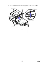
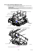
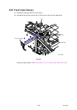
9.19 Laser Unit Flat Cable/Laser Unit
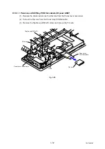
(1) Remove the six Taptite bind B M4x12 screws and four Taptite cup S M3x6 SR screws,
and remove the Scanner cover plate from the Main body.
Fig. 3-74
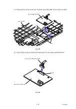
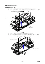
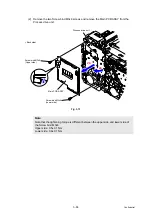
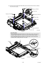
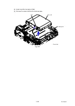
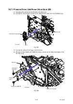
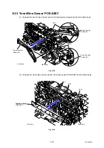
(2) Disconnect the Laser unit flat cable from the Laser unit and release the wiring.
Fig. 3-75
Harness routing: Refer to
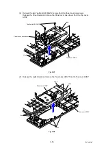
Assembling Note:
When assembling the six screws of the Taptite bind B M4x12, be sure to assemble
them in the order shown in the figure.
Taptite bind B M4x12
Taptite cup S M3x6 SR
Scanner cover plate
Main body
1
2
3
4
5 6
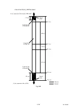
Taptite cup S M3x6 SR
Taptite cup S
M3x6 SR
Taptite bind B M4x12
Taptite bind B M4x12
Taptite bind
B M4x12
<Front side>
Laser unit flat cable
Laser unit
CN1
<Front side>


