7-7
Confidential
<Function>
Functions of each “
Service Mode
”.
9)
Factory Inspection Mode
This mode checks the operation of each sensor and solenoid to check the point with the
malfunction, when repair the machine.
• The machine goes into the inspection mode by a special operation when the power is
turned on.
• In the inspection mode, check that the
Status
LED (HL-5340D/ 5350DN/5350DNLT/
5370DW/5370DWT) or the
Data
LED (HL-5380DN) blink when the state of a sensor
or a switch is changed (from ON to OFF, or from OFF to ON).
<Sensor Inspection Check Procedure>
• Check sensors.
Manually activate the sensors and the actuators listed below, and verify that the
Status
LED is lit.
(When the state is changed continuously, the
Status
LED keeps blinking.)
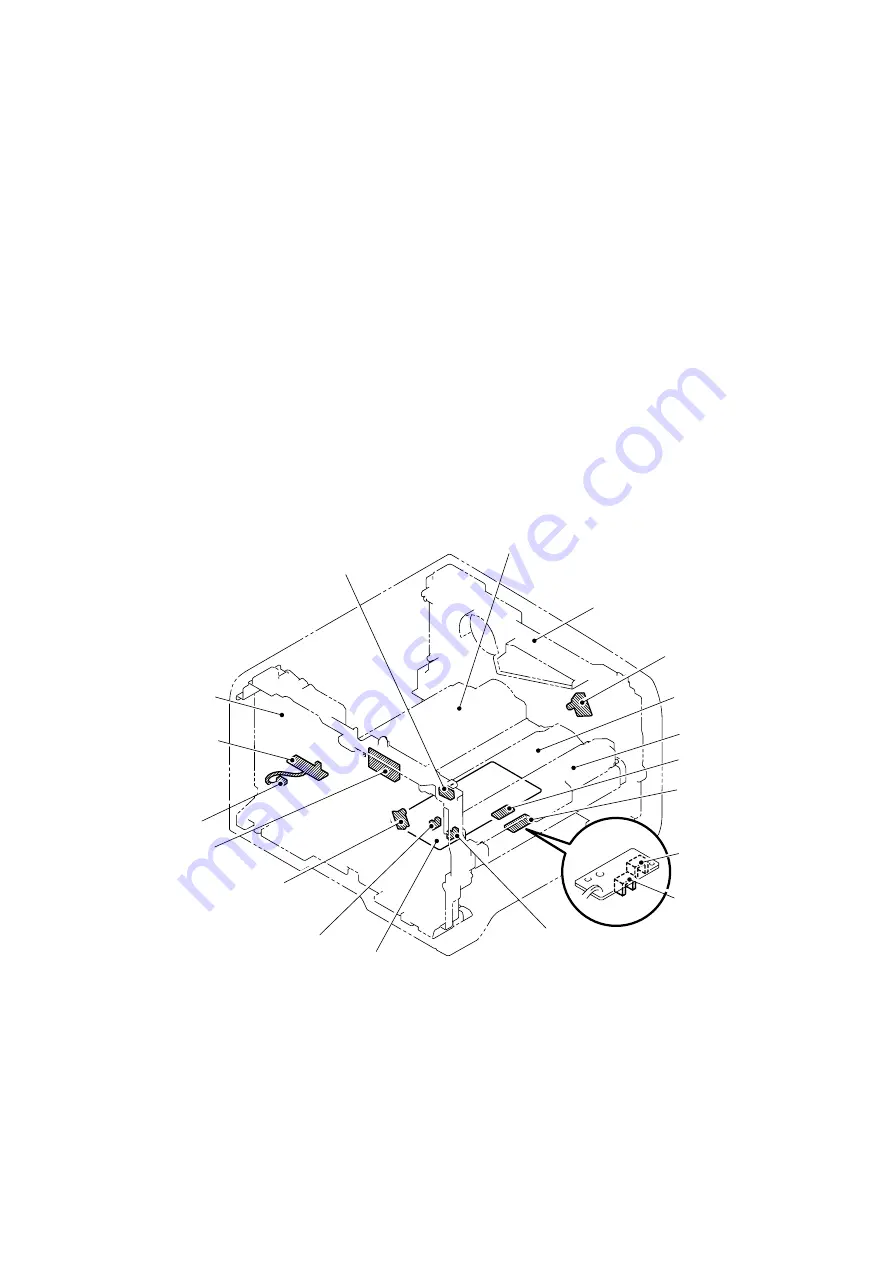
(Regist front sensor, Regist rear sensor, Paper eject sensor, New toner sensor, Front
cover sensor, PE sensor, Edge sensor, MP PE sensor, DX tray sensor)
* The toner sensor is unsupported.
Fig. 7-1
Chute
Frame R
Toner LED PCB
(Light emission)
Un supported
Toner sensor PCB
(Light reception) Un supported
Regist frame
Paper feed frame
MP PE sensor
PE EG sensor
PE sensor
Edge sensor
Regist front sensor
High-voltage PS PCB
Regist rear sensor
New toner sensor
(Relay front PCB)
DX tray sensor
Paper eject sensor
(Relay rear PCB)
Frame L
Front cover sensor
Summary of Contents for HL 5370DW
Page 12: ...CHAPTER 1 SPECIFICATIONS ...
Page 32: ...Confidential CHAPTER 2 THEORY OF OPERATION ...
Page 57: ...Confidential CHAPTER 3 ERROR INDICATION AND TROUBLESHOOTING ...
Page 109: ...Confidential CHAPTER 4 PERIODIC MAINTENANCE ...
Page 145: ...CHAPTER 5 DISASSEMBLY REASSEMBLY ...
Page 153: ...5 6 Confidential Fig 5 3 EM D110 4 places Separation pad ASSY ...
Page 154: ...5 7 Confidential 5 GEAR LAYOUT DRAWING Fig 5 4 ...
Page 213: ...5 66 Confidential 3 Remove the Gear 17 black Fig 5 86 4 Remove the Gear 17 white Fig 5 87 ...
Page 261: ...Confidential CHAPTER 6 ADJUSTMENTS AND UPDATING OF SETTINGS REQUIRED AFTER PARTS REPLACEMENT ...


