HL-3450CN SERVICE MANUAL
3-3
CHAPTER 3
INSTALLATION
1. CONDITIONS REQUIRED FOR INSTALLATION
Any Laser beam printer is likely to be influenced by the environment of the set-up location. If
the printer is set-up in an inappropriate location, the printer may not perform as expected.
Therefore, the following factors should be taken into consideration before deciding where to
set-up the printer.
1.1.
Environmental Conditions
The printer should not be set up in the locations referred to in the following items (1) through
(8) which specify inappropriate locations for set-up.
(1) Where it is likely to receive direct sunlight or similar light. (For example, next to a
window)
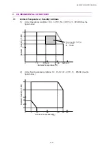
(2) Where it is likely to suffer a big difference in temperature and humidity between the
maximum and minimum levels. (Normal operation environment is within 10
q
C
a
32.5
q
C,
20
a
80%RH and without any condensation.)
(3) Where it is likely to be in a draft of cold air from an air-conditioner or warm air from a
heater, or to receive direct radiant heat.
(4) Where it is likely to be excessively dusty or be subject to corrosive gases such as
ammonia.
(5) Where it is likely that an ultrasonic humidifier will be used.
(6) Where it is likely to have poor ventilation.
(7) Where it is likely to have unstable conditions such as when the set-up table is not strong
enough.
(8) Where it is likely to be tilted (angle from the horizontal should not be greater than
r
1
q
).
1.2.
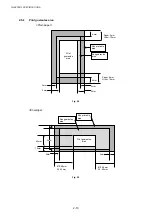
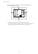
Basic Layout of Printer Set-up Location
CAUTION
In the case when the printer is set on a table, confirm that the media cassette does not to
protrude out beyond the edge of the table.
x
Any protrusion of the media cassette may catch a passersby and result in damage to the
printer.
x
Protrusion of the media cassette may cause the printer to tilt or fall over if the operator
leans against or applies excessive force to the media cassette, which may cause injuries.
Summary of Contents for HL-3450CN Series
Page 15: ...HL 3450CN SERVICE MANUAL xiii 3 Rating Label For US For Europe 4 Operation Label 5 Jam Label ...
Page 17: ...HL 3450CN SERVICE MANUAL CHAPTER 1 PRODUCT OUTLINE ...
Page 27: ...HL 3450CN SERVICE MANUAL CHAPTER 2 SPECIFICATIONS ...
Page 39: ...CHAPTER 3 INSTALLATION ...
Page 54: ...HL 3450CN SERVICE MANUAL CHAPTER 4 STRUCTURE OF SYSTEM COMPONENTS ...
Page 104: ...HL 3450CN SERVICE MANUAL 4 51 Main PCB Circuit Diagram 1 8 CODE B512137CIR 1 8 LJ8907001 NAME ...
Page 106: ...HL 3450CN SERVICE MANUAL 4 53 Main PCB Circuit Diagram 3 8 CODE B512137CIR 3 8 LJ8907001 NAME ...
Page 108: ...HL 3450CN SERVICE MANUAL 4 55 Main PCB Circuit Diagram 5 8 CODE B512137CIR 5 8 LJ8907001 NAME ...
Page 110: ...HL 3450CN SERVICE MANUAL 4 57 Main PCB Circuit Diagram 7 8 CODE B512137CIR 7 8 LJ8907001 NAME ...
Page 126: ...HL 3450CN SERVICE MANUAL CHAPTER 5 CONTROL PANEL OPERATION ...
Page 173: ...HL 3450CN SERVICE MANUAL CHAPTER 6 PERIODIC MAINTENANCE ...
Page 208: ...CHAPTER 7 DISASSEMBLY RE ASSEMBLY ...
Page 264: ...HL 3450CN SERVICE MANUAL CHAPTER 8 TROUBLESHOOTING ...
Page 310: ...HL 3450CN SERVICE MANUAL 8 47 5 IMAGE FAILURE 1 2 3 4 5 6 7 8 9 a 9 b 10 11 12 13 14 ...
Page 311: ...CHAPTER 8 TROUBLESHOOTING 8 48 15 a 15 b 16 17 18 19 20 21 22 23 24 25 26 27 28 244m m 29 ...

